Today we’d like to share a little 3D experiment with you. The idea is to show a mall map with all its floors in perspective. Additionally, we have a search in a sidebar that allows to filter mall spaces. Once a floor is selected, we show some pins as indicators for the different stores/spaces. When clicking on a pin, we show some more details of that space. We’ve mostly used CSS trickery for this, applying transitions that will rotate and move the levels by adding or removing classes. The levels are represented by inline SVGs.
The responsiveness of this concept is powered by the viewport unit vmin which allows us to use the smallest viewport side for sizing our elements.
This concept can be applied to any kind of floor map actually; any building that has several floors and spaces could be an interesting use case for this.
Attention: This is a highly experimental proof-of-concept. 3D and viewport units support is needed for this to work.
For the filtering and ordering of the spaces list in the sidebar we are using List.js, a great library for adding search, sort, filters and flexibility to tables, lists and various HTML elements.
The following is the initial view of the mall:
When clicking on a level or when clicking on a space in the sidebar, the respective level opens and the pins show:
Clicking on a pin will open the details for that space:
We hope you enjoy this little experiment and find it inspiring!
Today we’d like to share some isometric grid styles with you. The inspiration comes from the Hotchkiss website where an isometric, scrollable grid is shown with some cool hover effects. In our first experiment we created a scrollable grid just like the one seen on that site, with some hover effects that involve random rotations. The second demo shows some ideas for “static” grids that are not scrollable but that serve more kind of a decorative purpose.
For the grid layout we are using Metafizzy’s Masonry, the cascading grid layout library by David DeSandro.
Attention: Some of the techniques we are using are very experimental and won’t work in all browsers. Support for transform-style: preserve-3d is necessary for this demo.
The first demo shows how an isometric grid can be scrolled using the pagescroll.
In the second demo we show some ideas for different static/decorative styles. The grid is used as a background element that allows for some interaction. There are many possibilities and the following serve as inspiration:
Unfortunately, IE does not support transform-style: preserve-3d which breaks nested 3D elements. So this demo won’t work in the versions that don’t support it.
We hope you enjoy this experiment and find it inspiring!
Today we’d like to share a fun little Advent calendar with you. The idea is mainly inspired by the Singles 2016 page of Adult Swim. When hovering over the boxes, they rotate in a fun way and when we click on a box, all boxes disappear with an animation. Then some content shows up, also animating with individual effects. Additionally, we have the option to tilt the whole calendar according to the hover position.
We’ve created some demos for your inspiration and hope that you can use this as a base for your Christmas ideas.
For our Advent calendar we are using a Flexbox layout. The cubes are created from a “flat” structure and transformed into a multi-element structure that allows us to create the three-dimensional look. The respective content elements follow, each enclosed in a content__block:
The shared styles of all demos are defined in common.css while individual adjustments are made in style1.css, style2.css and style3.css.
Note that the initial structure has some data attributes that are used for the background color animation, the inactive class and to construct the title element that appears on hover. Have a look at the html files to see the markup.
Some interesting styles are the ones for building the cubes container and its cubes. Note that the cubes container gets created dynamically in our script. We explicitly use calc() here to show how the padding of the main calendar container is calculated. For seven boxes in a row, we subtract the width of them (counting with their margins) from the viewport width and divide it by two in order to get the padding for one side.
Today we’d like to share an experimental 3D layout with you. The idea is to show some information about a gallery’s exhibition in an interesting way. Each artist has a “room” in the gallery which shows the schedule for the exhibition. When clicking on one of the navigation buttons, we move away from the current room and proceed to the next (or previous) one with an animation.
For this experiment we are using the animation library anime.js by Julian Garnier and imagesLoaded by David DeSandro.
Attention: Highly experimental! Please view with a modern browser that supports CSS 3D Transforms and CSS Flexbox.
Here are some screenshots of the different views of the layout.
The initial view is the first room of the gallery:
When navigating, we move to the next/previous room:
When clicking on the menu icon in the top right corner, we rotate the whole room and get a view from the top. An overlay is shows that contains a menu:
The info button triggers a special “Inception” effect :) The images start floating away from the wall as if gravity is defied:
We hope you enjoy this little experiment and find it inspiring!
This set of demos explores 3D particle animations using three.js and easing. All of the particles and shapes in these demos are made from basic geometry/material/mesh sets in three.js, such as spheres, lines, and boxes.
The Concept
Making animations with a lot of small moving parts is a lot of fun. Applying different timing offsets and easings to each part or group can make for some interesting visualizations. And even though these can look great in 2D, adding subtle 3D perspective to your animations can make them even more visually appealing. Having the concept of a camera and 3D grid can also aid in the debugging and development of your animations. You can zoom in, zoom out, and view your animation from different perspectives to tune it perfectly.
Repeating animations like this is great for loader animations, backgrounds, and transitions. In these demos they are treated as site loader animations. I hope this inspires you to make your own 3D particle animations!
Benefits of three.js and a 3D Environment
Most of these animations could be made roughly comparable with something like SVG or 2D Canvas. However, adding subtle animations and positioning in a 3D perspective brings them to life. There are also performance benefits from working with three.js/WebGL. These animations only scratch the surface of what three.js is capable of. Custom geometries, materials, lighting, shadows, and shaders can take these to the next level. There is a lot of room to grow and expand from this fundamental starting point.
My goal with this set is to show what a baseline set of particle movements can achieve, with minimal flexing of three.js.
Debug Mode: Grid, Camera, and Timescale
To enter debug mode, click the debug icon in the top right. This will add a 3D grid to the scene, which gives a better sense of how everything is moving in 3D space. It adds camera controls, which allow you to zoom, rotate, and pan. And finally, a timescale slider is added to speed up, slow down, and pause the animation. This is useful for working on the timing and positioning of your animations.
#1: Rotating and Scaling Rings
This demo shows a series of rings that are scaling and rotating with slight offsets. The particles are also moving back and forth on the z-axis.
#2: Simplex Noise Lines
This demo shows a series of particles that form lines of two different colors. The particle position is being set by simplex noise, with tapered off magnitude near both edges. Over time, the lines rotate and move back and forth on the on z-axis.
#3: Circle Separations
This demo applies some simple physics to each particle. They all spawn in the center, and then push away from each other so that they all have their own space.
#4: Twisting Double Helix
This demo shows a double helix, almost like a simplified visualization of DNA. It is twisting and untwisting while rotating.
#5: Raindrops and Ripples
This demo shows a raindrop effect with rippling when they hit the surface of particles. The rain drops are made out of boxes that get stretched as they fall. When they hit, a ripple object is made that has a ring, and an invisible sphere that grows out that affects the particle positions and opacity.
#6: Spinning Fan
This demo shows three lines of particles that form a shallow cone shape. Each particle has an arc line with a randomized length trailing behind it.
#7: Square Lattice Blending
This demo shows boxes being stretched based on their position. The movement of each box is slightly offset. Four different color boxes are placed closely to each other and blended with additive blending to create the white color. As the boxes move, the colors lose their full overlap and reveal the underlying colors (red, green, blue, and magenta).
#8: Simplex Noise Particle System
This final demo uses a slightly different method for rendering the particles than the other demos. It uses THREE.BufferGeometry() and THREE.Points(), which allows us to render more particles at once and keep good performance. The particle movement is determined by simplex noise. Finally, additive blending is used to create a brighter effect when the particles overlap.
This library tackles the problem that you cannot handle the width of your lines with classic lines in Three.js. A MeshLine builds a strip of triangles billboarded to create a custom geometry instead of using the native WebGL GL_LINE method that does not support the width parameter.
These lines shaped as ribbons have a really interesting graphic style. They also have less vertices than a TubeGeometry usually used to create thick lines.
Animate a MeshLine
The only thing missing is the ability to animate lines without having to rebuild the geometry for each frame.
Based on what had already been started and how SVG Line animation works, I added three new parameters to MeshLineMaterial to visualize animated dashed line directly through the shader.
DashRatio: The ratio between what is visible or not (~0: more visible, ~1: less visible)
DashArray: The length of a dash and its space (0 == no dash)
DashOffset: The location where the first dash begins
Like with an SVG path, these parameters allow you to animate the entire traced line if they are correctly handled.
Here is a complete example of how to create and animate a MeshLine:
  // Build an array of points
  const segmentLength = 1;
  const nbrOfPoints = 10;
  const points = [];
  for (let i = 0; i < nbrOfPoints; i++) {
    points.push(i * segmentLength, 0, 0);
  }

  // Build the geometry
  const line = new MeshLine();
  line.setGeometry(points);
  const geometry = line.geometry;

  // Build the material with good parameters to animate it.
  const material = new MeshLineMaterial({
    transparent: true,
    lineWidth: 0.1,
    color: new Color('#ff0000'),
    dashArray: 2,     // always has to be the double of the line
    dashOffset: 0,    // start the dash at zero
    dashRatio: 0.75,  // visible length range min: 0.99, max: 0.5
  });

  // Build the Mesh
  const lineMesh = new Mesh(geometry, material);
  lineMesh.position.x = -4.5;

  // ! Assuming you have your own webgl engine to add meshes on scene and update them.
  webgl.add(lineMesh);

  // ! Call each frame
  function update() {
    // Check if the dash is out to stop animate it.
    if (lineMesh.material.uniforms.dashOffset.value < -2) return;

    // Decrement the dashOffset value to animate the path with the dash.
    lineMesh.material.uniforms.dashOffset.value -= 0.01;
  }
Create your own line style
Now that you know how to animate lines, I will show you some tips on how to customize the shape of your lines.
These classes smooth an array of points that is roughly positioned. They are perfect to build curved and fluid lines and keep control of them (length, orientation, turbulences…).
For instance, let’s add some turbulences to our previous array of points:
  const segmentLength = 1;
  const nbrOfPoints = 10;
  const points = [];
  const turbulence = 0.5;
  for (let i = 0; i < nbrOfPoints; i++) {
    // ! We have to wrapped points into a THREE.Vector3 this time
    points.push(new Vector3(
      i * segmentLength,
      (Math.random() * (turbulence * 2)) - turbulence,
      (Math.random() * (turbulence * 2)) - turbulence,
    ));
  }
Then, use one of these classes to smooth your array of lines before you create the geometry:
  // 2D spline
  // const linePoints = new Geometry().setFromPoints(new SplineCurve(points).getPoints(50));

  // 3D spline
  const linePoints = new Geometry().setFromPoints(new CatmullRomCurve3(points).getPoints(50));

  const line = new MeshLine();
  line.setGeometry(linePoints);
  const geometry = line.geometry;
And like that you create your smooth curved line!
Note that SplineCurve only smoothes in 2D (x and y axis) compared to CatmullRomCurve3 that takes into account three axes.
I recommend to use the SplineCurve, anyway. It is more performant to calculate lines and is often enough to create the desired curved effect.
For instance, my demos Confetti and Energy are only made with the SplineCurve method:
Use Raycasting
Another technique taken from a THREE.MeshLine example is using a Raycaster to scan a Mesh already present in the scene.
Thus, you can create your lines that follow the shape of an object:
  const radius = 4;
  const yMax = -4;
  const points = [];
  const origin = new Vector3();
  const direction = new Vector3();
  const raycaster = new Raycaster();

  let y = 0;
  let angle = 0;
  // Start the scan
  while (y < yMax) {
    // Update the orientation and the position of the raycaster
    y -= 0.1;
    angle += 0.2;
    origin.set(radius * Math.cos(angle), y, radius * Math.sin(angle));
    direction.set(-origin.x, 0, -origin.z);
    direction.normalize();
    raycaster.set(origin, direction);

    // Save the coordinates raycsted.
    // !Assuming the raycaster cross the object in the scene each time
    const intersect = raycaster.intersectObject(objectToRaycast, true);
    if (intersect.length) {
      points.push(
        intersect[0].point.x,
        intersect[0].point.y,
        intersect[0].point.z,
      );
    }
  }
This method is employed in the Boreal Sky demo. Here I used a sphere part as geometry to create the mesh objectToRaycast:
Now, you have enough tools to play and animate MeshLines. Many of these methods are inspired by the library’s examples. Feel free to explore these and share your own experiments and methods to create your own lines!
This tutorial is going to demonstrate how to draw a large number of particles with Three.js and an efficient way to make them react to mouse and touch input using shaders and an off-screen texture.
Attention: You will need an intermediate level of experience with Three.js. We will omit some parts of the code for brevity and assume you already know how to set up a Three.js scene and how to import your shaders — in this demo we are using glslify.
Instanced Geometry
The particles are created based on the pixels of an image. Our image’s dimensions are 320×180, or 57,600 pixels.
However, we don’t need to create one geometry for each particle. We can create only a single one and render it 57,600 times with different parameters. This is called geometry instancing. With Three.js we use InstancedBufferGeometry to define the geometry, BufferAttribute for attributes which remain the same for every instance and InstancedBufferAttribute for attributes which can vary between instances (i.e. colour, size).
The geometry of our particles is a simple quad, formed by 4 vertices and 2 triangles.
Next, we loop through the pixels of the image and assign our instanced attributes. Since the word position is already taken, we use the word offset to store the position of each instance. The offset will be the x,y of each pixel in the image. We also want to store the particle index and a random angle which will be used later for animation.
const indices = new Uint16Array(this.numPoints);
const offsets = new Float32Array(this.numPoints * 3);
const angles = new Float32Array(this.numPoints);

for (let i = 0; i < this.numPoints; i++) {
	offsets[i * 3 + 0] = i % this.width;
	offsets[i * 3 + 1] = Math.floor(i / this.width);

	indices[i] = i;

	angles[i] = Math.random() * Math.PI;
}

geometry.addAttribute('pindex', new THREE.InstancedBufferAttribute(indices, 1, false));
geometry.addAttribute('offset', new THREE.InstancedBufferAttribute(offsets, 3, false));
geometry.addAttribute('angle', new THREE.InstancedBufferAttribute(angles, 1, false));
Particle Material
The material is a RawShaderMaterial with custom shaders particle.vert and particle.frag.
The uniforms are described as follows:
uTime: elapsed time, updated every frame
uRandom: factor of randomness used to displace the particles in x,y
A simple vertex shader would output the position of the particles according to their offset attribute directly. To make things more interesting, we displace the particles using random and noise. And the same goes for particles’ sizes.
The fragment shader samples the RGB colour from the original image and converts it to greyscale using the luminosity method (0.21 R + 0.72 G + 0.07 B).
The alpha channel is determined by the linear distance to the centre of the UV, which essentially creates a circle. The border of the circle can be blurred out using smoothstep.
In our demo we set the size of the particles according to their brightness, which means dark particles are almost invisible. This makes room for some optimisation. When looping through the pixels of the image, we can discard the ones which are too dark. This reduces the number of particles and improves performance.
The optimisation starts before we create our InstancedBufferGeometry. We create a temporary canvas, draw the image onto it and call getImageData() to retrieve an array of colours [R, G, B, A, R, G, B … ]. We then define a threshold — hex #22 or decimal 34 — and test it against the red channel. The red channel is an arbitrary choice, we could also use green or blue, or even an average of all three channels, but the red channel is simple to use.
We also need to update the loop where we define offset, angle and pindex to take the threshold into account.
for (let i = 0, j = 0; i < this.numPoints; i++) {
	if (originalColors[i * 4 + 0] <= threshold) continue;

	offsets[j * 3 + 0] = i % this.width;
	offsets[j * 3 + 1] = Math.floor(i / this.width);

	indices[j] = i;

	angles[j] = Math.random() * Math.PI;

	j++;
}
Interactivity
Considerations
There are many different ways of introducing interaction with the particles. For example, we could give each particle a velocity attribute and update it on every frame based on its proximity to the cursor. This is a classic technique and it works very well, but it might be a bit too heavy if we have to loop through tens of thousands of particles.
A more efficient way would be to do it in the shader. We could pass the cursor’s position as a uniform and displace the particles based on their distance from it. While this would perform a lot faster, the result could be quite dry. The particles would go to a given position, but they wouldn’t ease in or out of it.
Chosen Approach
The technique we chose in our demo was to draw the cursor position onto a texture. The advantage is that we can keep a history of cursor positions and create a trail. We can also apply an easing function to the radius of that trail, making it grow and shrink smoothly. Everything would happen in the shader, running in parallel for all the particles.
In order to get the cursor’s position we use a Raycaster and a simple PlaneBufferGeometry the same size of our main geometry. The plane is invisible, but interactive.
Interactivity in Three.js is a topic on its own. Please see this example for reference.
When there is an intersection between the cursor and the plane, we can use the UV coordinates in the intersection data to retrieve the cursor’s position. The positions are then stored in an array (trail) and drawn onto an off-screen canvas. The canvas is passed as a texture to the shader via the uniform uTouch.
In the vertex shader the particles are displaced based on the brightness of the pixels in the touch texture.
This tutorial is going to demonstrate how to build a wave animation effect for a grid of building models using three.js and TweenMax (GSAP).
Attention: This tutorial assumes you already have a some understanding of how three.js works.
If you are not familiar, I highly recommend checking out the official documentation and examples .
The idea is to create a grid of random buildings, that reveal based on their distance towards the camera. The motion we are trying to get is like a wave passing through, and the farthest elements will be fading out in the fog.
We also modify the scale of each building in order to create some visual randomness.
Getting started
First we have to create the markup for our demo. It’s a very simple boilerplate since all the code will be running inside a canvas element:
createScene() {
  this.scene = new THREE.Scene();

  this.renderer = new THREE.WebGLRenderer({ antialias: true, alpha: true });
  this.renderer.setSize(window.innerWidth, window.innerHeight);

  this.renderer.shadowMap.enabled = true;
  this.renderer.shadowMap.type = THREE.PCFSoftShadowMap;

  document.body.appendChild(this.renderer.domElement);

  // this is the line that will give us the nice foggy effect on the scene
  this.scene.fog = new THREE.Fog(this.fogConfig.color, this.fogConfig.near, this.fogConfig.far);
}
Camera
Let’s add a camera for to scene:
createCamera() {
  const width = window.innerWidth;
  const height = window.innerHeight;

  this.camera = new THREE.PerspectiveCamera(20, width / height, 1, 1000);

  // set the distance our camera will have from the grid
  // this will give us a nice frontal view with a little perspective
  this.camera.position.set(3, 16, 111);

  this.scene.add(this.camera);
}
Ground
Now we need to add a shape to serve as the scene’s ground
addFloor() {
  const width = 200;
  const height = 200;
  const planeGeometry = new THREE.PlaneGeometry(width, height);

  // all materials can be changed according to your taste and needs
  const planeMaterial = new THREE.MeshStandardMaterial({
    color: '#fff',
    metalness: 0,
    emissive: '#000000',
    roughness: 0,
  });

  const plane = new THREE.Mesh(planeGeometry, planeMaterial);

  planeGeometry.rotateX(- Math.PI / 2);

  plane.position.y = 0;

  this.scene.add(plane);
}
Load 3D models
Before we can build the grid, we have to load our models.
loadModels(path, onLoadComplete) {
  const loader = new THREE.OBJLoader();

  loader.load(path, onLoadComplete);
}

onLoadModelsComplete(model) {
  // our buildings.obj file contains many models
  // so we have to traverse them to do some initial setup

  this.models = [...model.children].map((model) => {
    // since we don't control how the model was exported
    // we need to scale them down because they are very big

    // scale model down
    const scale = .01;
    model.scale.set(scale, scale, scale);

    // position it under the ground
    model.position.set(0, -14, 0);

    // allow them to emit and receive shadow
    model.receiveShadow = true;
    model.castShadow = true;

    return model;
  });

  // our list of models are now setup
}
Ambient Light
addAmbientLight() {
  const ambientLight = new THREE.AmbientLight('#fff');

  this.scene.add(ambientLight);
}
Grid Setup
Now we are going to place those models in a grid layout.
createGrid() {
  // define general bounding box of the model
  const boxSize = 3;

  // define the min and max values we want to scale
  const max = .009;
  const min = .001;

  const meshParams = {
    color: '#fff',
    metalness: .58,
    emissive: '#000000',
    roughness: .18,
  };

  // create our material outside the loop so it performs better
  const material = new THREE.MeshPhysicalMaterial(meshParams);

  for (let i = 0; i < this.gridSize; i++) {
    for (let j = 0; j < this.gridSize; j++) {

      // for every iteration we pull out a random model from our models list and clone it
      const building = this.getRandomBuiding().clone();

      building.material = material;

      building.scale.y = Math.random() * (max - min + .01);

      building.position.x = (i * boxSize);
      building.position.z = (j * boxSize);

      // add each model inside a group object so we can move them easily
      this.group.add(building);

      // store a reference inside a list so we can reuse it later on
      this.buildings.push(building);
    }
  }

  this.scene.add(this.group);

  // center our group of models in the scene
  this.group.position.set(-this.gridSize - 10, 1, -this.gridSize - 10);
}
Spot Light
We also add a SpotLight to the scene for a nice light effect.
Before we animate the models into the scene, we want to sort them according to their z distance to the camera.
sortBuildingsByDistance() {
  this.buildings.sort((a, b) => {
    if (a.position.z > b.position.z) {
      return 1;
    }

    if (a.position.z < b.position.z) {
      return -1;
    }

    return 0;
  }).reverse();
}
Animate Models
This is the function where we go through our buildings list and animate them. We define the duration and the delay of the animation based on their position in the list.
If you use Facebook, you might have seen the update of 3D photos for the news feed and VR. With special phone cameras that capture the distance between the subject in the foreground and the background, 3D photos bring scenes to life with depth and movement. We can recreate this kind of effect with any photo, some image editing and a little bit of coding.
Usually, these kind of effects would rely on either Three.js or Pixi.js, the powerful libraries that come with many useful features and simplifications when coding. Today we won’t use any libraries but go with the native WebGL API.
So let’s dig in.
Getting started
So, for this effect we’ll go with the native WebGL API. A great place to help you get started with WebGL is webglfundamentals.org. WebGL is usually being berated for its verboseness. And there is a reason for that. The foundation of all fullcreen shader effects (even if they are 2D) is some sort of plane or mesh, or so called quad, which is stretched over the whole screen. So, speaking of being verbose, while we would simply write THREE.PlaneGeometry(1,1) in three.js which creates the 1×1 plane, here is what we need in plain WebGL:
let vertices = new Float32Array([
	  -1, -1,
	  1, -1,
	  -1, 1,
	  1, 1,
	])
	let buffer = gl.createBuffer();
	gl.bindBuffer( gl.ARRAY_BUFFER, buffer );
	gl.bufferData( gl.ARRAY_BUFFER, vertices, gl.STATIC_DRAW );
Now that we have our plane, we can apply vertex and fragment shaders to it.
Preparing the image
For our effect to work, we need to create a depth map of the image. The main principle for building a depth map is that we’ve got to separate some parts of the image depending on their Z position, i.e. being far or close, hence isolate the foreground from the background.
For that, we can open the image in Photoshop and paint gray areas over the original photo in the following way:
This image shows some mountains where you can see that the closer the objects are to the camera, the brighter the area is painted in the depth map. Let’s see in the next section why this kind of shading makes sense.
Shaders
The rendering logic is mostly happening in shaders. As described in the MDN web docs:
A shader is a program, written using the OpenGL ES Shading Language (GLSL), that takes information about the vertices that make up a shape and generates the data needed to render the pixels onto the screen: namely, the positions of the pixels and their colors. There are two shader functions run when drawing WebGL content: the vertex shader and the fragment shader.
The most interesting part will happen in a fragment shader. Let’s load the two images there:
void main(){
    vec4 depth = texture2D(depthImage, uv);
    gl_FragColor = texture2D(originalImage, uv); // just showing original photo
}
Remember, the depth map image is black and white. For shaders, color is just a number: 1 is white and 0 is pitch black. The uv variable is a two dimensional map storing information on which pixel to show. With these two things we can use the depth information to move the pixels of the original photo a little bit.
Because the texture is black and white, we can just take the red channel (depth.r), and multiply it to the mouse position value on the screen. That means, the brighter the pixel is, the more it will move with the mouse. On the other hand, dark pixels will just stay in place. It’s so simple, yet, it results in such a nice 3D illusion of an image.
Of course, shaders are capable of doing all kinds of other crazy things, but I hope you like this small experiment of “faking” a 3D movement. Let me know what you think about it, and I hope to see your creations with this!
We will be looking at how to pull apart SVGs in 3D space with Three.js and React, using abstractions that allow us to break the scene graph into reusable components.
React and Three.js, what’s the problem?
My background in the past had more to do with front-end work than design, and React has been my preferred tool for a couple of years now. I like it because it pretty much maps the way i think. The ideas in my head are puzzle-pieces, which in React turn to composable components. It makes prototyping faster, and from a visual/design standpoint, it’s even fun, because it allows you to play around without repercussions. If everything is a self-contained lego-brick, you can rip it out, place it here, or there, and observe the result from different angles and perspectives. Especially for visual coding this can make a difference.
The problems that arise when handling programming tasks in an imperative way are always the same. Once we have created a sufficiently complex dependency-graph then things tend to be cobbled together, which causes the whole to be less flexible. Adding, updating or deleting items in sync with state and other operations can get complex. Orchestrating animations makes it even worse, because now you need to await animations to conclude before you continue with other operations and so on. Without a clear component-model it can be a reasonable challenge to keep it all together.
We run into this when working with user interfaces, as well as when creating scenes with Three.js, which can lend to especially unwieldy structures as it forces us to create a ton of objects that we have to track, mutate and manage. But React can solve that, too.
Think of React as a standard that defines what a component is and how it functions. React needs a so called “reconciler” to tell it what to do with these components and how to render them into a host. The browsers dom is a host, hence the react-dom package, which instructs React about the dom. React-native is another one you may be familiar with, but really there are dozens, reaching into all kinds of platforms, from AR, VR, console shells to, you guessed it, Three.js. The reconciler we will be using in this tutorial is called react-three-fiber, it renders components into a Three.js scene graph. Think of it as a portal into Three.js.
Let’s build!
Setting up the scene
Our portal into Three.js will be react-three-fiber’s “Canvas” component. Everything that goes in there will be cast into Three.js-native objects. The following will create a responsive canvas with some lights in it.
Our goal is to extract SVG paths, once we have that we can display them in all sorts of interesting ways. We will be using fairly simple sketches for that, they won’t create many layers and the effect will be less pronounced.
In order to transform SVGs into shape geometries we use Three.js’s SVGLoader. The following will give us a nested array of objects that contains the shapes and colors. We collect the index, too, which we will be using to offset the z-vector.
const svgResource = new Promise(resolve =>
  new loader().load(url, shapes =>
    resolve(
      flatten(
        shapes.map((group, index) =>
          group.toShapes(true).map(shape => ({ shape, color: group.color, index }))
        )
      )
    )
  )
)
Next we define a “Shape” component which renders a single shape. Each shape is offset 50 units by its own index.
function Shape({ shape, position, color, opacity, index }) {
  return (
    <mesh position={[0, 0, index * 50]}>
      <meshPhongMaterial attach="material" color={color} />
      <shapeBufferGeometry attach="geometry" args={[shape]} />
    </mesh>
  )
}
All we are missing now is a component that maps through the shapes we have created. Since the resource we have created is a promise we have to await its resolved state. Once it has loaded, we wrote it into the local component state and forward each shape to the “Shape” component we have just created.
If you wanted to animate Three.js you would most likely do it manually and use tools like GSAP. And since we want to animate elements that go in and out you need to have some system in place that orchestrates it, which is not an easy task to pull off.
Here comes the nice part, we are rendering React components and that opens up a lot of possibilities. We can use pretty much everything that exists in the eco system, including animation and transition tools. In this case we use react-spring.
Really all we need to do is convert out shapes into a transition-group. A transition group is something that watches state for changes and helps to retain and transition old state until it can be safely removed. In react-springs case it is called “useTransition”. It takes the original data, shapes in this case, keys in order to identify changes in the data-set, and a couple of lifecycles in which we can define what happens when state is added, removed or changed.
The following takes care of everything. If shapes are added, they will transition into the scene in a trailed motion. If shapes are removed, they will transition out.
useTransition creates an array of objects which contain generated keys, the data items (our shapes) and animated properties. We spread everything over the Shape component. Now we just need to prepare that component to receive animated values and we are done.
react-spring exports a little helper called “animated”, as well as a shortcut called “a”. If you extend any element with it, it will be able to handle these properties. Basically, if you had a div, it would become a.div, if you had a mesh, it now becomes a.mesh.
I hope you had fun! You will find detailed explanations for everything in the respective docs for react-three-fiber and react-spring. The full code for the original demo can be found here.
For this tutorial, I’ll assume you are comfortable with JavaScript, HTML and CSS.
I’m going to do something a little bit different here in the interest of actually teaching you, and not making you copy/paste parts that aren’t all that relevant to this tutorial, we’re going to start with all of the CSS in place. The CSS really is just for the dressing around the app, it focusses on the UI only. That being said, each time we paste some HTML, I’ll explain quickly what the CSS does. Let’s get started.
Part 1: The 3D model
If you want to skip this part entirely, feel free to do so, but it may pay to read it just so you have a deeper understanding of how everything works.
This isn’t a 3D modelling tutorial, but I will explain how the model is set up in Blender, and if you’d like to create something of your own, change a free model you found somewhere online, or instruct someone you’re commissioning. Here’s some information about how our chairs 3D model is authored.
The 3D model for this tutorial is hosted and included within the JavaScript, so don’t worry about downloading or having to do any of this unless you’d like to look further into using Blender, and learning how to create your own model.
Scale
The scale is set to approximately what it would be in the real world; I don’t know if this is important, but it feels like the right thing to do, so why not?
Layering and naming conventions
This part is important: each element of the object you want to customize independently needs to be its own object in the 3D scene, and each item needs to have a unique name. Here we have back, base, cushions, legs and supports. Note that if you have say, three items all called supports, Blender is going to name them as supports, supports.001, supports.002. That doesn’t matter, because in our JavaScript we’ll be using includes(“supports”) to find all of those objects that contain the string supports in it.
Placement
The model should be placed at the world origin, ideally with its feet on the floor. It should ideally be facing the right way, but this can easily be rotated via JavaScript, no harm, no foul.
Setting up for export
Before exporting, you want to use Blender’s Smart UV unwrap option. Without going too much into detail, this makes textures keep its aspect ratio in tact as it wraps around the different shapes in your model without stretching in weird ways (I’d advise reading up on this option only if you’re making your own model).
You want to be sure to select all of your objects, and apply your transformations. For instance, if you changed the scale or transformed it in any way, you’re telling Blender that this is the new 100% scale, instead of it still being 32.445% scale if you scaled it down a bit.
File Format
Apparently Three.js supports a bunch of 3D object file formats, but the one it recommends is glTF (.glb). Blender supports this format as an export option, so no worries there.
Part 2: Setting up our environment
Go ahead and fork this pen, or start your own one and copy the CSS from this pen. This is a blank pen with just the CSS we’re going to be using in this tutorial.
If you don’t choose to fork this, grab the HTML as well; it has the responsive meta tags and Google fonts included.
We’re going to use three dependencies for this tutorial. I’ve included comments above each that describe what they do. Copy these into your HTML, right at the bottom:
<!-- The main Three.js file -->
<script src='https://cdnjs.cloudflare.com/ajax/libs/three.js/108/three.min.js'></script>

<!-- This brings in the ability to load custom 3D objects in the .gltf file format. Blender allows the ability to export to this format out the box -->
<script src='https://cdn.jsdelivr.net/gh/mrdoob/Three.js@r92/examples/js/loaders/GLTFLoader.js'></script>

<!-- This is a simple to use extension for Three.js that activates all the rotating, dragging and zooming controls we need for both mouse and touch, there isn't a clear CDN for this that I can find -->
<script src='https://threejs.org/examples/js/controls/OrbitControls.js'></script>
Let’s include the canvas element. The entire 3D experience gets rendered into this element, all other HTML will be UI around this. Place the canvas at the bottom of your HTML, above your dependencies.
<!-- The canvas element is used to draw the 3D scene -->
<canvas id="c"></canvas>
Now, we’re going to create a new Scene for Three.js. In your JavaScript, lets make a reference to this scene like so:
// Init the scene
const scene = new THREE.Scene();
Below this, we’re going to reference our canvas element
const canvas = document.querySelector('#c');
Three.js requires a few things to run, and we will get to all of them. The first was scene, the second is a renderer. Let’s add this below our canvas reference. This creates a new WebGLRenderer, we’re passing our canvas to it, and we’ve opted in for antialiasing, this creates smoother edges around our 3D model.
// Init the renderer
const renderer = new THREE.WebGLRenderer({canvas, antialias: true});
And now we’re going to append the renderer to the document body
document.body.appendChild(renderer.domElement);
The CSS for the canvas element is just stretching it to 100% height and width of the body, so your entire page has now turned black, because the entire canvas is now black!
Our scene is black, we’re on the right track here.
The next thing Three.js needs is an update loop, basically this is a function that runs on each frame draw and is really important to the way our app will work. We’ve called our update function animate(). Let’s add it below everything else in our JavaScript.
function animate() {
  renderer.render(scene, camera);
  requestAnimationFrame(animate);
}

animate();
Note that we’re referencing a camera here, but we haven’t set one up yet. Let’s add one now.
At the top of your JavaScript, we’ll add a variable called cameraFar. When we add our camera to our scene, it’s going to be added at position 0,0,0. Which is where our chair is sitting! so cameraFar is the variable that tells our camera how far off this mark to move, so that we can see our chair.
var cameraFar = 5;
Now, above our function animate() {….} lets add a camera.
// Add a camera
var camera = new THREE.PerspectiveCamera( 50, window.innerWidth / window.innerHeight, 0.1, 1000);
camera.position.z = cameraFar;
camera.position.x = 0;
This is a perspective camera, with the field of view of 50, the size of the whole window/canvas, and some default clipping planes. The planes determine how near or far the camera should be before the object isn’t rendered. It’s not something we need to pay attention to in our app.
Our scene is still black, let’s set a background color.
At the top, above our scene reference, add a background color variable called BACKGROUND_COLOR.
const BACKGROUND_COLOR = 0xf1f1f1;
Notice how we used 0x instead of # in our hex? These are hexadecimal numbers, and the only thing you need to remember about that is that its not a string the way you’d handle a standard #hex variable in JavaScript. It’s an integer and it starts with 0x.
Below our scene reference, let’s update the scenes background color, and add some fog of the same color off in the distance, this is going to help hide the edges of the floor once we add that in.
const BACKGROUND_COLOR = 0xf1f1f1;

// Init the scene
const scene = new THREE.Scene();

// Set background
scene.background = new THREE.Color(BACKGROUND_COLOR );
scene.fog = new THREE.Fog(BACKGROUND_COLOR, 20, 100);
Now it’s an empty world. It’s hard to tell that though, because there’s nothing in there, nothing casting shadows. We have a blank scene. Now it’s time to load in our model.
Part 3: Loading the model
We’re going to add the function that loads in models, this is provided by our second dependency we added in our HTML.
Before we do that though, let’s reference the model, we’ll be using this variable quite a bit. Add this at the top of your JavaScript, above your BACKGROUND_COLOR. Let’s also add a path to the model. I’ve hosted it for us, it’s about 1Mb in size.
var theModel;
const MODEL_PATH =  "https://s3-us-west-2.amazonaws.com/s.cdpn.io/1376484/chair.glb";
Now we can create a new loader, and use the load method. This sets theModel as our 3D models entire scene. We’re also going to set the size for this app, the right size seems to be about twice as big as it’s loaded. Thirdly, we’re going to offset the y position by -1 to bring it down a little bit, and finally we’re going to add the model to the scene.
The first parameter is the model’s filepath, the second is a function that runs once the resource is loaded, the third is undefined for now but can be used for a second function that runs while the resource is loading, and the final parameter handles errors.
Add this below our camera.
// Init the object loader
var loader = new THREE.GLTFLoader();

loader.load(MODEL_PATH, function(gltf) {
  theModel = gltf.scene;

// Set the models initial scale
  theModel.scale.set(2,2,2);

  // Offset the y position a bit
  theModel.position.y = -1;

  // Add the model to the scene
  scene.add(theModel);

}, undefined, function(error) {
  console.error(error)
});
At this point you should be seeing a stretched, black, pixelated chair. As awful as it looks, this is right so far. So don’t worry!
Along with a camera, we need lights. The background isn’t affected by lights, but if we added a floor right now, it would also be black (dark). There are a number of lights available for Three.js, and a number of options to tweak all of them. We’re going to add two: a hemisphere light, and a directional light. The settings are also sorted for our app, and they include position and intensity. This is something to play around with if you ever adopt these methods in your own app, but for now, lets use the ones I’ve included. Add these lights below your loader.
// Add lights
var hemiLight = new THREE.HemisphereLight( 0xffffff, 0xffffff, 0.61 );
    hemiLight.position.set( 0, 50, 0 );
// Add hemisphere light to scene
scene.add( hemiLight );

var dirLight = new THREE.DirectionalLight( 0xffffff, 0.54 );
    dirLight.position.set( -8, 12, 8 );
    dirLight.castShadow = true;
    dirLight.shadow.mapSize = new THREE.Vector2(1024, 1024);
// Add directional Light to scene
    scene.add( dirLight );
Your chair looks marginally better! Before we continue, here’s our JavaScript so far:
var cameraFar = 5;
var theModel;

const MODEL_PATH =  "https://s3-us-west-2.amazonaws.com/s.cdpn.io/1376484/chair.glb";

const BACKGROUND_COLOR = 0xf1f1f1;
// Init the scene
const scene = new THREE.Scene();
// Set background
scene.background = new THREE.Color(BACKGROUND_COLOR );
scene.fog = new THREE.Fog(BACKGROUND_COLOR, 20, 100);

const canvas = document.querySelector('#c');

// Init the renderer
const renderer = new THREE.WebGLRenderer({canvas, antialias: true});

document.body.appendChild(renderer.domElement);

// Add a camerra
var camera = new THREE.PerspectiveCamera( 50, window.innerWidth / window.innerHeight, 0.1, 1000);
camera.position.z = cameraFar;
camera.position.x = 0;

// Init the object loader
var loader = new THREE.GLTFLoader();

loader.load(MODEL_PATH, function(gltf) {
  theModel = gltf.scene;

// Set the models initial scale
  theModel.scale.set(2,2,2);

  // Offset the y position a bit
  theModel.position.y = -1;

  // Add the model to the scene
  scene.add(theModel);

}, undefined, function(error) {
  console.error(error)
});

// Add lights
var hemiLight = new THREE.HemisphereLight( 0xffffff, 0xffffff, 0.61 );
    hemiLight.position.set( 0, 50, 0 );
// Add hemisphere light to scene
scene.add( hemiLight );

var dirLight = new THREE.DirectionalLight( 0xffffff, 0.54 );
    dirLight.position.set( -8, 12, 8 );
    dirLight.castShadow = true;
    dirLight.shadow.mapSize = new THREE.Vector2(1024, 1024);
// Add directional Light to scene
    scene.add( dirLight );

function animate() {
  renderer.render(scene, camera);
  requestAnimationFrame(animate);
}

animate();
Here’s what we should be looking at right now:
Let’s fix the pixelation and the stretching. Three.js needs to update the canvas size when it shifts, and it needs to set its internal resolution not only to the dimensions of the canvas, but also the device pixel ratio of the screen (which is much higher on phones).
Lets head to the bottom of our JavaScript, below where we call animate(), and add this function. This function basically listens to both, the canvas size and the window size, and returns a boolean depending on whether the two sizes are the same or not. We will use that function inside the animate function to determine whether to re-render the scene. This function is also going to take into account the device pixel ratio to be sure that the canvas is sharp on mobile phones too.
Add this function at the bottom of your JavaScript.
function resizeRendererToDisplaySize(renderer) {
  const canvas = renderer.domElement;
  var width = window.innerWidth;
  var height = window.innerHeight;
  var canvasPixelWidth = canvas.width / window.devicePixelRatio;
  var canvasPixelHeight = canvas.height / window.devicePixelRatio;

  const needResize = canvasPixelWidth !== width || canvasPixelHeight !== height;
  if (needResize) {

    renderer.setSize(width, height, false);
  }
  return needResize;
}
Now update your animate function to look like this:
I need to mention a couple things before we continue:
The chair is backwards, this is my bad. We’re going to simply rotate the model on its Y position
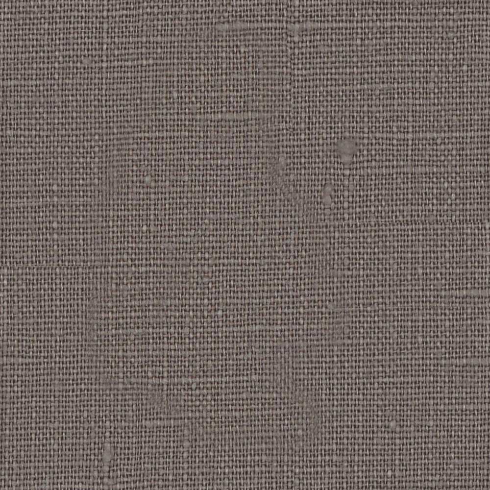
The supports are black? but the rest is white? This is because the model has some material information that has been imported with it that I had set up in Blender. This doesn’t matter, because we’re going to add a function that lets us define textures in our app, and add them to different areas of the chair when the model loads. So, if you have a wood texture and a denim texture (spoiler: we will), we will have the ability to set these on load without the user having to choose them. So the materials on the chair right now don’t matter all that much.
Humour me quickly, head to the loader function, and remember where we set the scale to (2,2,2)? Lets add this under it:
// Set the models initial scale
  theModel.scale.set(2,2,2);

  theModel.rotation.y = Math.PI;
Yeah, much better, sorry about that. One more thing: Three.js doesn’t have support for degrees as far as I know (?), everyone appears to be using Math.PI. This equals 180 degrees, so if you want something angled at a 45 degree angle, you’d use Math.PI / 4.
Okay, we’re getting there! We need a floor though, without a floor there can’t really be any shadows right?
Add a floor, what we’re doing here is creating a new plane (a two-dimensional shape, or a three-dimensional shape with no height).
Add this below our lights…
// Floor
var floorGeometry = new THREE.PlaneGeometry(5000, 5000, 1, 1);
var floorMaterial = new THREE.MeshPhongMaterial({
  color: 0xff0000,
  shininess: 0
});

var floor = new THREE.Mesh(floorGeometry, floorMaterial);
floor.rotation.x = -0.5 * Math.PI;
floor.receiveShadow = true;
floor.position.y = -1;
scene.add(floor);
Let’s take a look at whats happening here.
First, we made a geometry, we won’t be needing to make another geometry in Three.js in this tutorial, but you can make all sorts.
Secondly, notice how we also made a new MeshPhongMaterial and set a couple options. It’s color, and it’s shininess. Check out some of Three.js other materials later on. Phong is great because you can adjust its reflectiveness and specular highlights. There is also MeshStandardMaterial which has support for more advanced texture aspects such as metallic and ambient occlusion, and there is also the MeshBasicMaterial, which doesn’t support shadows. We will just be creating Phong materials in this tutorial.
We created a variable called floor and merged the geometry and material into a Mesh.
We set the floor’s rotation to be flat, opted in for the ability to receive shadows, moved it down the same way we moved the chair down, and then added it to the scene.
We should now be looking at this:
We will leave it red for now, but, where are the shadows? There’s a couple of things we need to do for that. First, under our const renderer, lets include a couple of options:
// Init the renderer
const renderer = new THREE.WebGLRenderer({canvas, antialias: true});

renderer.shadowMap.enabled = true;
renderer.setPixelRatio(window.devicePixelRatio);
We’ve set the pixel ratio to whatever the device’s pixel ratio is, not relevant to shadows, but while we’re there, let’s do that. We’ve also enabled shadowMap, but there are still no shadows? That’s because the materials we have on our chair are the ones brought in from Blender, and we want to author some of them in our app.
Our loader function includes the ability to traverse the 3D model. So, head to our loader function and add this in below the theModel = gltf.scene; line. For each object in our 3D model (legs, cushions, etc), we’re going to to enable to option to cast shadows, and to receive shadows. This traverse method will be used again later on.
It looks arguably worse than it did before, but at least theres a shadow on the floor! This is because our model still has materials brought in from Blender. We’re going to replace all of these materials with a basic, white PhongMaterial.
Lets create another PhongMaterial and add it above our loader function:
// Initial material
const INITIAL_MTL = new THREE.MeshPhongMaterial( { color: 0xf1f1f1, shininess: 10 } );
This is a great starting material, it’s a slight off-white, and it’s only a little bit shiny. Cool!
We could just add this to our chair and be done with it, but some objects may need a specific color or texture on load, and we can’t just blanket the whole thing with the same base color, the way we’re going to do this is to add this array of objects under our initial material.
We’re going to traverse through our 3D model again and use the childID to find different parts of the chair, and apply the material to it (set in the mtl property). These childID’s match the names we gave each object in Blender, if you read that section, consider yourself informed!
Below our loader function, let’s add a function that takes the the model, the part of the object (type), and the material, and sets the material. We’re also going to add a new property to this part called nameID so that we can reference it later.
// Function - Add the textures to the models
function initColor(parent, type, mtl) {
  parent.traverse((o) => {
   if (o.isMesh) {
     if (o.name.includes(type)) {
          o.material = mtl;
          o.nameID = type; // Set a new property to identify this object
       }
   }
 });
}
Now, inside our loader function, just before we add our model to the scene (scene.add(theModel);)
Let’s run that function for each object in our INITIAL_MAP array:
  // Set initial textures
  for (let object of INITIAL_MAP) {
    initColor(theModel, object.childID, object.mtl);
  }
Finally, head back to our floor, and change the color from red (0xff0000) to a light grey(0xeeeeee).
// Floor
var floorGeometry = new THREE.PlaneGeometry(5000, 5000, 1, 1);
var floorMaterial = new THREE.MeshPhongMaterial({
  color: 0xeeeeee, // <------- Here
  shininess: 0
});
It’s worth mentioning here that 0xeeeeee is different to our background color. I manually dialed this in until the floor with the lights shining on it matched the lighter background color. We’re now looking at this:
Congratulations, we’ve got this far! If you got stuck anywhere, fork this pen or investigate it until you find the issue.
Part 4: Adding controls
For real though this is a very small part, and is super easy thanks to our third dependency OrbitControls.js.
Above our animate function, we add this in our controls:
// Add controls
var controls = new THREE.OrbitControls( camera, renderer.domElement );
controls.maxPolarAngle = Math.PI / 2;
controls.minPolarAngle = Math.PI / 3;
controls.enableDamping = true;
controls.enablePan = false;
controls.dampingFactor = 0.1;
controls.autoRotate = false; // Toggle this if you'd like the chair to automatically rotate
controls.autoRotateSpeed = 0.2; // 30
Inside the animate function, at the top, add:
controls.update();
So our controls variable is a new OrbitControls class. We’ve set a few options that you can change here if you’d like. These include the range in which the user is allowed to rotate around the chair (above and below). We’ve disabled panning to keep the chair centered, enabled dampening to give it weight, and included auto rotate ability if you choose to use them. This is currently set to false.
Try click and drag your chair, you should be able to explore the model with full mouse and touch functionality!
Our app currently doesn’t do anything, so this next part will focus on changing our colors. We’re going to add a bit more HTML. Afterwards, I’ll explain a bit about what the CSS is doing.
Add this below your canvas element:
<div class="controls">
<!-- This tray will be filled with colors via JS, and the ability to slide this panel will be added in with a lightweight slider script (no dependency used for this) -->
 <div id="js-tray" class="tray">
     <div id="js-tray-slide" class="tray__slide"></div>
 </div>
</div>
Basically, the .controls DIV is stuck to the bottom of the screen, the .tray is set to be 100% width of the body, but its child, .tray__slide is going to fill with swatches and can be as wide as it needs. We’re going to add the ability to slide this child to explore colors as one of the final steps of this tutorial.
Let’s start by adding in a couple colors. At the top of our JavaScript, lets add an array of five objects, each with a color property.
Note that these neither have # or 0x to represent the hex. We will use these colors for both in functions. Also, it’s an object because we will be able to add other properties to this color, like shininess, or even a texture image (spoiler: we will, and we will).
Lets make swatches out of these colors!
First, let’s reference our tray slider at the top of our JavaScript:
Right at the bottom of our JavaScript, lets add a new function called buildColors and immediately call it.
// Function - Build Colors
function buildColors(colors) {
  for (let [i, color] of colors.entries()) {
    let swatch = document.createElement('div');
    swatch.classList.add('tray__swatch');

      swatch.style.background = "#" + color.color;

    swatch.setAttribute('data-key', i);
    TRAY.append(swatch);
  }
}

buildColors(colors);
We’re now creating swatches out of our colors array! Note that we set the data-key attribute to the swatch, we’re going to use this to look up our color and make them into materials.
Below our new buildColors function, let’s add an event handler to our swatches:
// Swatches
const swatches = document.querySelectorAll(".tray__swatch");

for (const swatch of swatches) {
  swatch.addEventListener('click', selectSwatch);
}
Our click handler calls a function called selectSwatch. This function is going to build a new PhongMaterial out of the color and call another function to traverse through our 3d model, find the part it’s meant to change, and update it!
Below the event handlers we just added, add the selectSwatch function:
function selectSwatch(e) {
     let color = colors[parseInt(e.target.dataset.key)];
     let new_mtl;

      new_mtl = new THREE.MeshPhongMaterial({
          color: parseInt('0x' + color.color),
          shininess: color.shininess ? color.shininess : 10

        });

    setMaterial(theModel, 'legs', new_mtl);
}
This function looks up our color by its data-key attribute, and creates a new material out of it.
This won’t work yet, we need to add the setMaterial function, (see the final line of the function we just added).
Take note of this line: setMaterial(theModel, ‘legs’, new_mtl);. Currently we’re just passing ‘legs’ to this function, soon we will add the ability to change out the different sections we want to update. But first, lets add the zcode>setMaterial
function.
Below this function, add the setMaterial function:
function setMaterial(parent, type, mtl) {
  parent.traverse((o) => {
   if (o.isMesh && o.nameID != null) {
     if (o.nameID == type) {
          o.material = mtl;
       }
   }
 });
}
This function is similar to our initColor function, but with a few differences. It checks for the nameID we added in the initColor, and if its the same as the parameter type, it adds the material to it.
Our swatches can now create a new material, and change the color of the legs, give it a go! Here’s everything we have so far in a pen. Investigate it if you’re lost.
We can now change the color of the legs, which is awesome, but let’s add the ability to select the part our swatch should add its material to. Include this HTML just below the opening body tag, I’ll explain the CSS below.
<!-- These toggle the the different parts of the chair that can be edited, note data-option is the key that links to the name of the part in the 3D file -->
<div class="options">
    <div class="option --is-active" data-option="legs">
        <img src="https://s3-us-west-2.amazonaws.com/s.cdpn.io/1376484/legs.svg" alt=""/>
    </div>
    <div class="option" data-option="cushions">
        <img src="https://s3-us-west-2.amazonaws.com/s.cdpn.io/1376484/cushions.svg" alt=""/>
    </div>
    <div class="option" data-option="base">
        <img src="https://s3-us-west-2.amazonaws.com/s.cdpn.io/1376484/base.svg" alt=""/>
    </div>
    <div class="option" data-option="supports">
        <img src="https://s3-us-west-2.amazonaws.com/s.cdpn.io/1376484/supports.svg" alt=""/>
    </div>
    <div class="option" data-option="back">
        <img src="https://s3-us-west-2.amazonaws.com/s.cdpn.io/1376484/back.svg" alt=""/>
    </div>
</div>
This is just a collection of buttons with custom icons in each. The .options DIV is stuck to the side of the screen via CSS (and shifts a bit with media queries). Each .option DIV is just a white square, that has a red border on it when a –is-active class is added to it. It also includes a data-option attribute that matches our nameID, so we can identify it. Lastly, the image element has a CSS property called pointer-events: none so that the event stays on the parent even if you click the image.
Lets add another variable at the top of our JavaScript called activeOptions and by default let’s set it to ‘legs’:
var activeOption = 'legs';
Now head back to our selectSwatch function and update that hard-coded ‘legs’ parameter to activeOption
setMaterial(theModel, activeOption, new_mtl);
Now all we need to do is create a event handler to change out activeOption when an option is clicked!
Let’s add this above our const swatches and selectSwatch function.
// Select Option
const options = document.querySelectorAll(".option");

for (const option of options) {
  option.addEventListener('click',selectOption);
}

function selectOption(e) {
  let option = e.target;
  activeOption = e.target.dataset.option;
  for (const otherOption of options) {
    otherOption.classList.remove('--is-active');
  }
  option.classList.add('--is-active');
}
We’ve added the selectOption function, which sets the activeOption to our event targets data-option value, and toggles the –is-active class. Thats it!
But why stop here? An object could look like anything, it can’t all be the same material. A chair with no wood or fabric? Lets expand our color selection a little bit. Update your color array to this:
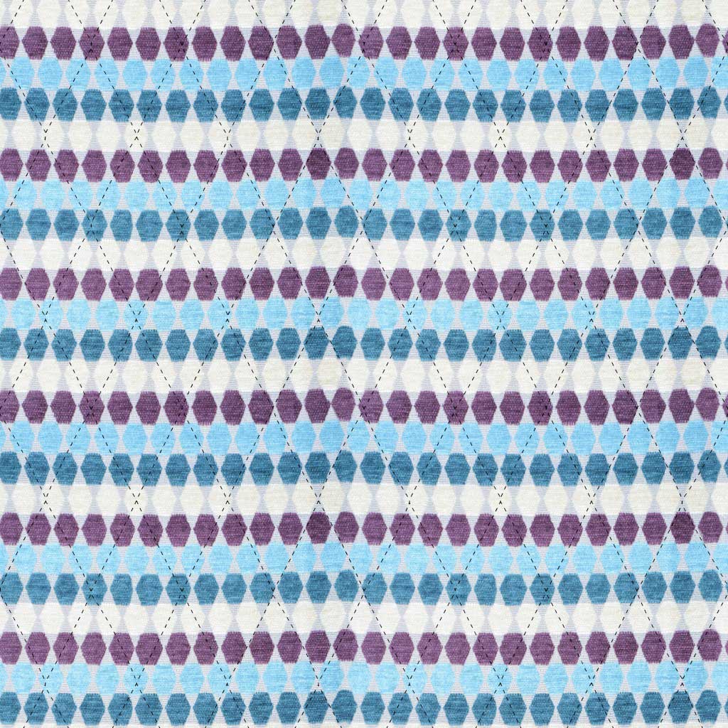
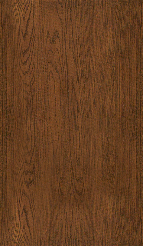
The top two are now textures. We’ve got wood and denim. We also have two new properties, size and shininess. Size is how often to repeat a pattern, so the larger the number, the more dense the pattern is, or more simply put – the more it repeats.
There are two function we need to update to add this ability. Firstly, lets head to the buildColors function and update to this
// Function - Build Colors

function buildColors(colors) {
  for (let [i, color] of colors.entries()) {
    let swatch = document.createElement('div');
    swatch.classList.add('tray__swatch');

    if (color.texture)
    {
      swatch.style.backgroundImage = "url(" + color.texture + ")";
    } else
    {
      swatch.style.background = "#" + color.color;
    }

    swatch.setAttribute('data-key', i);
    TRAY.append(swatch);
  }
}
Now its checking to see if its a texture, if it is, it’s going to set the swatches background to be that texture, neat!
Notice the gap between the 5th and 6th swatch? The final batch of colors, which I will provide, is grouped into color schemes of 5 colors per scheme. So each scheme will have that small divider in it, this is set in the CSS and will make more sense in the final product.
The second function we’re going to update is the selectSwatch function. Update it to this:
function selectSwatch(e) {
     let color = colors[parseInt(e.target.dataset.key)];
     let new_mtl;

    if (color.texture) {

      let txt = new THREE.TextureLoader().load(color.texture);

      txt.repeat.set( color.size[0], color.size[1], color.size[2]);
      txt.wrapS = THREE.RepeatWrapping;
      txt.wrapT = THREE.RepeatWrapping;

      new_mtl = new THREE.MeshPhongMaterial( {
        map: txt,
        shininess: color.shininess ? color.shininess : 10
      });
    }
    else
    {
      new_mtl = new THREE.MeshPhongMaterial({
          color: parseInt('0x' + color.color),
          shininess: color.shininess ? color.shininess : 10

        });
    }

    setMaterial(theModel, activeOption, new_mtl);
}
To explain what’s going on here, this function will now check if it’s a texture. If it is, it’s going to create a new texture using the Three.js TextureLoader method, it’s going to set the texture repeat using our size values, and set the wrapping of it (this wrapping option seems to work best, I’ve tried the others, so lets go with it), then its going to set the PhongMaterials map property to the texture, and finally use the shininess value.
If it’s not a texture, it uses our older method. Note that you can set a shininess property to any of our original colors!
Important: if your textures just remain black when you try add them. Check your console. Are you getting cross domain CORS errors? This is a CodePen bug and I’ve done my best to try fix it. These assets are hosted directly in CodePen via a Pro feature so its unfortunate to have to battle with this. Apparently, the best bet here is to not visit those image URLs directly, otherwise I recommend signing up to Cloudinary and using their free tier, you may have better luck pointing your textures there.
Here’s a pen with the textures working on my end at least:
I’ve had projects get run passed clients with a big button that is begging to be pressed, positively glistening with temptation to even just hover over it, and them and their co-workers (Dave from accounts) come back with feedback about how they didn’t know there was anything to be pressed (screw you, Dave).
So let’s add some calls to action. First, let’s chuck in a patch of HTML above the canvas element:
<!-- Just a quick notice to the user that it can be interacted with -->
<span class="drag-notice" id="js-drag-notice">Drag to rotate 360°</span>
The CSS places this call-to-action above the chair, it’s a nice big button that instructs the user to drag to rotate the chair. It just stays there though? We will get to that.
Let’s spin the chair once it’s loaded first, then, once the spin is done, let’s hide that call-to-action.
First, lets add a loaded variable to the top of our JavaScript and set it to false:
var loaded = false;
Right at the bottom of your JavaScript, add this function
// Function - Opening rotate
let initRotate = 0;

function initialRotation() {
  initRotate++;
if (initRotate <= 120) {
    theModel.rotation.y += Math.PI / 60;
  } else {
    loaded = true;
  }
}
This simply rotates the the model 360 degrees within the span of 120 frames (around 2 seconds at 60fps), and we’re going to run this in the animate function to call it for 120 frames, once its done, it’s going to set loaded to true in our animate function. Here’s how it will look in its entirely with the new code at the end there:
We check that theModel doesn’t equal null, and that the variable loaded is false, and we run that function for 120 frames, at which point the function switches to loaded = true, and our animate function ignores it.
You should have a nice spinning chair. When that chair stops is a great time to remove our call-to-action.
In the CSS, there’s a class that can be added to that call-to-action that will hide it with an animation, this animation has a delay of 3 seconds, so let’s add that class at the same time the rotation starts.
At the top of your JavaScript we will reference it:
Awesome! These hang off the page though, right at the bottom of your JavaScript, add this function, it will allow you to drag the swatches panel with mouse and touch. For the interest of keeping on topic, I won’t delve too much into how it works.
Okay, let’s finish it off with a the final two touches, and we’re done!
Let’s update our .controls div to include this extra call-to-action:
<div class="controls">
<div class="info">
<div class="info__message">
<p><strong> Grab </strong> to rotate chair. <strong> Scroll </strong> to zoom. <strong> Drag </strong> swatches to view more.</p>
</div>
</div>
<!-- This tray will be filled with colors via JS, and the ability to slide this panel will be added in with a lightweight slider script (no dependency used for this) -->
<div id="js-tray" class="tray">
<div id="js-tray-slide" class="tray__slide"></div>
</div>
</div>
Note that we have a new info section that includes some instructions on how to control the app.
Finally, let’s add a loading overlay so that our app is clean while everything loads, and we will remove it once the model is loaded.
Add this to the top of our HTML, below the body tag.
<!-- The loading element overlays all else until the model is loaded, at which point we remove this element from the DOM -->
<div class="loading" id="js-loader"><div class="loader"></div></div>
Here’s the thing about our loader, in order for it to load first, we’re going to add the CSS to the head tag instead of being included in the CSS. So simply add this CSS just above the closing head tag.
You can also check out the demo hosted here on Codrops.
Thank you for sticking with me!
This is a big tutorial. If you feel I made a mistake somewhere, please let me know in the comments, and thanks again for following with me as we create this absolute unit.
Blurry is a set of scripts that allow you to easily visualize simple geometrical shapes with a bokeh/depth of field effect of an out-of-focus camera. It uses Three.js internally to make it easy to develop the shaders and the WebGL programs required to run it.
The bokeh effect is generated by using millions of particles to draw the primitives supported by the library. These particles are then accumulated in a texture and randomly displaced in a circle depending on how far away they are from the focal plane.
These are some of the scenes I’ve recently created using Blurry:
Since the library itself is very simple and you don’t need to know more than three functions to get started, I’ve decided to write this walk-through of a scene made with Blurry. It will teach you how to use various tricks to create geometrical shapes often found in the works of generative artists. This will also hopefully show you how simple tools can produce interesting and complex looking results.
In this little introduction to Blurry we’ll try to recreate the following scene, by using various techniques borrowed from the world of generative art:
Starting out
You can download the repo here and serve index.html from a local server to render the scene that is currently coded inside libs/createScene.js. You can rotate, zoom and pan around the scene as with any Three.js project using OrbitControls.js.
There are also some additional key-bindings to change various parameters of the renderer, such as the focal length, exposure, bokeh strength and more. These are visible at the bottom left of the screen.
All the magic happens inside libs/createScene.js, where you can implement the two functions required to render something with Blurry. All the snippets defined in this article will end up inside createScene.js.
The most important function we’ll need to implement to recreate the scene shown at the beginning of the article is createScene(), which will be called by the other scripts just before the renderer pushes the primitives to the GPU for the actual rendering of the scene.
The other function we’ll define is setGlobals(), which is used to define the parameters of the shaders that will render our scene, such as the strength of the bokeh effect, the exposure, background color, etc.
Let’s head over to createScene.js, remove everything that’s already coded in there, and define setGlobals() as:
There’s an explanation for each of these parameters in the Readme of the GitHub repo. The important info at the moment is that the camera will start positioned at (x: 0, y: 0, z: 115) and the cameraFocalDistance (the distance from the camera where our primitives will be in focus) will be set at 100, meaning that every point 100 units away from the camera will be in focus.
Another variable to consider is pointsPerFrame, which is used internally to assign a set number of points to all the primitives to render in a single frame. If you find that your GPU is struggling with 50000, lower that value.
Before we start implementing createScene(), let’s first define some initial global variables that will be useful later:
let rand, nrand;
let vec3 = function(x,y,z) { return new THREE.Vector3(x,y,z) };
I’ll explain the usage of each of these variables as we move along; vec3() is just a simple shortcut to create Three.js vectors without having to type THREE.Vector3(…) each time.
Very often I find the need to “repeat” the sequence of randomly generated numbers I had in a bugged scene. If I had to rely on the standard Math.random() function, each page-refresh would give me different random numbers, which is why I’ve included a seeded random number generator in the project. Utils.setRandomSeed(…) will take a string as a parameter and use that as the seed of the random numbers that will be generated by Utils.rand(), the seeded generator that is used in place of Math.random() (though you can still use that if you want).
The functions rand & nrand will be used to generate random values in the interval [0 … 1] for rand, and [-1 … +1] for nrand.
Let’s draw some lines
At the moment you can only draw two simple primitives in Blurry: lines and quads. We’ll focus on lines in this article. Here’s the code that generates 10 consecutive straight lines:
lines is simply a global array used to store the lines to render. Every line we .push() into the array will be rendered.
v1 and v2 are the two vertices of the line. c1 and c2 are the colors associated to each vertex as an RGB triplet. Note that Blurry is not restricted to the [0…1] range for each component of the RGB color. In this case using 5 for each component will give us a white line.
If you did everything correctly up until now, you’ll see 10 straight lines in the screen as soon as you launch index.html from a local server.
function computeWeb() {
    // how many curved lines to draw
    let r2 = 17;
    // how many "straight pieces" to assign to each of these curved lines
    let r1 = 35;
    for(let j = 0; j < r2; j++) {
        for(let i = 0; i < r1; i++) {
            // definining the spherical coordinates of the two vertices of the line we're drawing
            let phi1 = j / r2 * Math.PI * 2;
            let theta1 = i / r1 * Math.PI - Math.PI * 0.5;

            let phi2 = j / r2 * Math.PI * 2;
            let theta2 = (i+1) / r1 * Math.PI - Math.PI * 0.5;

            // converting spherical coordinates to cartesian
            let x1 = Math.sin(phi1) * Math.cos(theta1);
            let y1 = Math.sin(theta1);
            let z1 = Math.cos(phi1) * Math.cos(theta1);

            let x2 = Math.sin(phi2) * Math.cos(theta2);
            let y2 = Math.sin(theta2);
            let z2 = Math.cos(phi2) * Math.cos(theta2);

            lines.push(
                new Line({
                    v1: vec3(x1,y1,z1).multiplyScalar(15),
                    v2: vec3(x2,y2,z2).multiplyScalar(15),
                    c1: vec3(5,5,5),
                    c2: vec3(5,5,5),
                })
            );
        }
    }
}
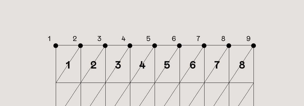
The goal here is to create a bunch of vertical lines that follow the shape of a sphere. Since we can’t make curved lines, we’ll break each line along this sphere in tiny straight pieces. (x1,y1,z1) and (x2,y2,z2) will be the endpoints of the line we’ll draw in each iteration of the loop. r2 is used to decide how many vertical lines in the surface of the sphere we’ll be drawing, whereas r1 is the amount of tiny straight pieces that we’re going to use for each one of the curved lines we’ll draw.
The phi and theta variables represent the spherical coordinates of both points, which are then converted to Cartesian coordinates before pushing the new line into the lines array.
Each time the outer loop (j) is entered, phi1 and phi2 will decide at which angle the vertical line will start (for the moment, they’ll hold the same exact value). Every iteration inside the inner loop (i) will construct the tiny pieces creating the vertical line, by slightly incrementing the theta angle at each iteration.
After the conversion, the resulting Cartesian coordinates will be multiplied by 15 world units with .multiplyScalar(15), thus the curved lines that we’re drawing are placed on the surface of a sphere which has a radius of exactly 15.
To make things a bit more interesting, let’s twist these vertical lines a bit with this simple change:
let phi1 = (j + i * 0.075) / r2 * Math.PI * 2;
...
let phi2 = (j + (i+1) * 0.075) / r2 * Math.PI * 2;
If we twist the phi angles a bit as we move up the line while we’re constructing it, we’ll end up with:
And as a last change, let’s swap the z-axis of both points with the y-axis:
Now the fun part begins. To recreate these type of intersections between the lines we just did
…we’ll need to play a bit with ray-plane intersections. Here’s an overview of what we’ll do:
Given the lines we made in our 3D scene, we’re going to create an infinite plane with a random direction and we’ll intersect this plane with all the lines we have in the scene. Then we’ll pick one of these lines intersecting the plane (chosen at random) and we’ll find the closest line to it that is also intersected by the plane.
Let’s use a figure to make the example a bit easier to digest:
Let’s assume all the segments in the picture are the lines of our scene that intersected the random plane. The red line was chosen randomly out of all the intersected lines. Every line intersects the plane at a specific point in 3D space. Let’s call “x” the point of contact of the red line with the random plane.
The next step is to find the closest point to “x”, from all the other contact points of the other lines that were intersected by the plane. In the figure the green point “y” is the closest.
As soon as we have these two points “x” and “y”, we’ll simply create another line connecting them.
If we run this process several times (creating a random plane, intersecting our lines, finding the closest point, making a new line) we’ll end up with the result we want. To make it possible, let’s define findIntersectingEdges() as:
function findIntersectingEdges(center, dir) {

    let contactPoints = [];
    for(line of lines) {
        let ires = intersectsPlane(
            center, dir,
            line.v1, line.v2
        );

        if(ires === false) continue;

        contactPoints.push(ires);
    }

    if(contactPoints.length < 2) return;
}
The two parameters of findIntersectingEdges() are the center of the 3D plane and the direction that the plane is facing towards. contactPoints will store all the points of intersection between the lines of our scene and the plane, intersectsPlane() will tell us if a given line intersects a plane. If the returned value ires isn’t undefined, which means there’s a point of intersection stored inside the ires variable, we’ll save the ires variable in the contactPoints array.
intersectsPlane() is defined as:
function intersectsPlane(planePoint, planeNormal, linePoint, linePoint2) {

    let lineDirection = new THREE.Vector3(linePoint2.x - linePoint.x, linePoint2.y - linePoint.y, linePoint2.z - linePoint.z);
    let lineLength = lineDirection.length();
    lineDirection.normalize();

    if (planeNormal.dot(lineDirection) === 0) {
        return false;
    }

    let t = (planeNormal.dot(planePoint) - planeNormal.dot(linePoint)) / planeNormal.dot(lineDirection);
    if (t > lineLength) return false;
    if (t < 0) return false;

    let px = linePoint.x + lineDirection.x * t;
    let py = linePoint.y + lineDirection.y * t;
    let pz = linePoint.z + lineDirection.z * t;

    let planeSize = Infinity;
    if(vec3(planePoint.x - px, planePoint.y - py, planePoint.z - pz).length() > planeSize) return false;

    return vec3(px, py, pz);
}
I won’t go over the details of how this function works, if you want to know more check the original version of the function here.
Let’s now go to step 2: Picking a random contact point (we’ll call it randCp) and finding its closest neighbor contact point. Append this snippet at the end of findIntersectingEdges():
function findIntersectingEdges(center, dir) {
    ...
    ...

    let randCpIndex = Math.floor(rand() * contactPoints.length);
    let randCp = contactPoints[randCpIndex];

    // let's search the closest contact point from randCp
    let minl = Infinity;
    let minI = -1;

    // iterate all contact points
    for(let i = 0; i < contactPoints.length; i++) {
        // skip randCp otherwise the closest contact point to randCp will end up being... randCp!
        if(i === randCpIndex) continue;

        let cp2 = contactPoints[i];

        // 3d point in space of randCp
        let v1 = vec3(randCp.x, randCp.y, randCp.z);
        // 3d point in space of the contact point we're testing for proximity
        let v2 = vec3(cp2.x, cp2.y, cp2.z);

        let sv = vec3(v2.x - v1.x, v2.y - v1.y, v2.z - v1.z);
        // "l" holds the euclidean distance between the two contact points
        let l = sv.length();

        // if "l" is smaller than the minimum distance we've registered so far, store this contact point's index as minI
        if(l < minl) {
            minl = l;
            minI = i;
        }
    }

    let cp1 = contactPoints[randCpIndex];
    let cp2 = contactPoints[minI];

    // let's create a new line out of these two contact points
    lines.push(
        new Line({
            v1: vec3(cp1.x, cp1.y, cp1.z),
            v2: vec3(cp2.x, cp2.y, cp2.z),
            c1: vec3(2,2,2),
            c2: vec3(2,2,2),
        })
    );
}
Now that we have our routine to test intersections against a 3D plane, let’s use it repeatedly against the lines that we already made in the surface of the sphere. Append the following code at the end of computeWeb():
function computeWeb() {

    ...
    ...

    // intersect many 3d planes against all the lines we made so far
    for(let i = 0; i < 4500; i++) {
        let x0 = nrand() * 15;
        let y0 = nrand() * 15;
        let z0 = nrand() * 15;

        // dir will be a random direction in the unit sphere
        let dir = vec3(nrand(), nrand(), nrand()).normalize();
        findIntersectingEdges(vec3(x0, y0, z0), dir);
    }
}
We’re almost done! To make the depth of field effect more prominent we’re going to fill the scene with little sparkles. So, it’s now time to define the last function we were missing:
let v0 = vec3(nrand(), nrand(), nrand()).normalize().multiplyScalar(18 + rand() * 65);
Here we’re creating a 3D vector with three random values between -1 and +1. Then, by doing .normalize() we’re making it a “unit vector”, which is a vector whose length is exactly 1.
If you drew many points by using this method (choosing three random components between [-1, +1] and then normalizing the vector) you’d notice that all the points you draw end up on the surface of a sphere (which have a radius of exactly one).
Since the sphere we’re drawing in computeWeb() has a radius of exactly 15 units, we want to make sure that all our sparkles don’t end up inside the sphere generated in computeWeb().
We can make sure that all points are far enough from the sphere by multiplying each vector component by a scalar that is bigger than the sphere radius with .multiplyScalar(18 … and then adding some randomness to it by adding + rand() * 65.
let c = 1.325 * (0.3 + rand() * 0.7);
c is a multiplier for the color intensity of the sparkle we’re computing. At a minimum, it will be 1.325 * (0.3), if rand() ends up at the highest possible value, c will be 1.325 * (1).
The line if(rand() > 0.9) c *= 4; can be read as “every 10 sparkles, make one whose color intensity is four times bigger than the others”.
The two calls to lines.push() are drawing a horizontal line of size s, and center v0, and a vertical line of size s, and center v0. All the sparkles are in fact little “plus signs”.
The final step to our small journey with Blurry is to change the color of our lines to match the colors of the finished scene.
Before we do so, I’ll give a very simplistic explanation of the algebraic operation called “dot product”. If we plot two unit vectors in 3D space, we can measure how “similar” the direction they’re pointing to is.
Two parallel unit vectors will have a dot product of 1 while orthogonal unit vectors will instead have a dot product of 0. Opposite unit vectors will result in a dot product of -1.
Take this picture as a reference for the value of the dot product depending on the two input unit vectors:
We can use this operation to calculate “how close” two directions are to each other, and we’ll use it to fake diffuse lighting and create the effect that two light sources are lighting up the scene.
Here’s a drawing which will hopefully make it easier to understand what we’ll do:
The red and white dot on the surface of the sphere has the red unit vector direction associated with it. Now let’s imagine that the violet vectors represent light emitted from a directional light source, and the green vector is the opposite vector of the violet vector (in algebraic terms the green vector is the negation of the violet vector). If we take the dot product between the red and the green vector, we’ll get an estimate of how much the two vectors point to the same direction. The bigger the value is, the bigger the amount of light received at that point will be. The intuitive reasoning behind this process is essentially to imagine each of the points in our lines as if they were very small planes. If these little planes are facing toward the light source, they’ll absorb and reflect more light from it.
Remember though that the dot operation can also return negative values. We’ll catch that by making sure that the minimum value returned by that function is greater or equal than 0.
Let’s now code what we said so far with words and define two new global variables just before the definition of createScene():
let lightDir0 = vec3(1, 1, 0.2).normalize();
let lightDir1 = vec3(-1, 1, 0.2).normalize();
You can think about both variables as two green vectors in the picture above, pointing to two different directional light sources.
We’ll also create a normal1 variable which will be used as our “red vector” in the picture above and calculate the dot products between normal1 and the two light directions we just added. Each light direction will have a color associated to it. After we calculate with the dot products how much light is reflected from both light directions, we’ll just sum the two colors together (we’ll sum the RGB triplets) and use that as the new color of the line we’ll create.
Lets finally append a new snippet to the end of computeWeb() which will change the color of the lines we computed in the previous steps:
function computeWeb() {
    ...

    // recolor edges
    for(line of lines) {
        let v1 = line.v1;

        // these will be used as the "red vectors" of the previous example
        let normal1 = v1.clone().normalize();

        // lets calculate how much light normal1
        // will get from the "lightDir0" light direction (the white light)
        // we need Math.max( ... , 0.1) to make sure the dot product doesn't get lower than
        // 0.1, this will ensure each point is at least partially lit by a light source and
        // doesn't end up being completely black
        let diffuse0 = Math.max(lightDir0.dot(normal1), 0.1);
        // lets calculate how much light normal1
        // will get from the "lightDir1" light direction (the reddish light)
        let diffuse1 = Math.max(lightDir1.dot(normal1), 0.1);

        let firstColor = [diffuse0, diffuse0, diffuse0];
        let secondColor = [2 * diffuse1, 0.2 * diffuse1, 0];

        // the two colors will represent how much light is received from both light directions,
        // so we'll need to sum them togheter to create the effect that our scene is being lit by two light sources
        let r1 = firstColor[0] + secondColor[0];
        let g1 = firstColor[1] + secondColor[1];
        let b1 = firstColor[2] + secondColor[2];

        let r2 = firstColor[0] + secondColor[0];
        let g2 = firstColor[1] + secondColor[1];
        let b2 = firstColor[2] + secondColor[2];

        line.c1 = vec3(r1, g1, b1);
        line.c2 = vec3(r2, g2, b2);
    }
}
Keep in mind what we’re doing is a very, very simple way to recreate diffuse lighting, and it’s incorrect for many reasons, starting from the fact we’re only considering the first vertex of each line, and assigning the calculated light contribution to both, the first and second vertex of the line, without considering the fact that the second vertex might be very far away from the first vertex, thus ending up with a different normal vector and consequently different light contributions. But we’ll live with this simplification for the purpose of this article.
Let’s also update the lines created with computeSparkles() to reflect these changes as well:
function computeSparkles() {
    for(let i = 0; i < 5500; i++) {
        let v0 = vec3(nrand(), nrand(), nrand()).normalize().multiplyScalar(18 + rand() * 65);

        let c = 1.325 * (0.3 + rand() * 0.7);
        let s = 0.125;

        if(rand() > 0.9) {
            c *= 4;
        }

        let normal1 = v0.clone().normalize();

        let diffuse0 = Math.max(lightDir0.dot(normal1), 0.1);
        let diffuse1 = Math.max(lightDir1.dot(normal1), 0.1);

        let r = diffuse0 + 2 * diffuse1;
        let g = diffuse0 + 0.2 * diffuse1;
        let b = diffuse0;

        lines.push(new Line({
            v1: vec3(v0.x - s, v0.y, v0.z),
            v2: vec3(v0.x + s, v0.y, v0.z),

            c1: vec3(r * c, g * c, b * c),
            c2: vec3(r * c, g * c, b * c),
        }));

        lines.push(new Line({
            v1: vec3(v0.x, v0.y - s, v0.z),
            v2: vec3(v0.x, v0.y + s, v0.z),

            c1: vec3(r * c, g * c, b * c),
            c2: vec3(r * c, g * c, b * c),
        }));
    }
}
And that’s it!
The scene you’ll end up seeing will be very similar to the one we wanted to recreate at the beginning of the article. The only difference will be that I’m calculating the light contribution for both computeWeb() and computeSparkles() as:
let diffuse0 = Math.max(lightDir0.dot(normal1) * 3, 0.15);
let diffuse1 = Math.max(lightDir1.dot(normal1) * 2, 0.2 );
If you made it this far, you’ll now know how this very simple library works and hopefully you learned a few tricks for your future generative art projects!
This little project only used lines as primitives, but you can also use textured quads, motion blur, and a custom shader pass that I’ve used recently to recreate volumetric light shafts. Look through the examples in libs/scenes/ if you’re curious to see those features in action.
If you have any question about the library or if you’d like to suggest a feature/change feel free to open an issue in the github repo. I’d love to hear your suggestions!
Ever had a personal website dedicated to your work and wondered if you should include a photo of yourself in there somewhere? I recently figured I’d go a couple steps further and added a fully interactive 3D version of myself that watched the user’s cursor as they navigated around my screen. And ass if that wasn’t enough, you could even click on me and I’d do stuff. This tutorial shows you how to do the same with a model we chose named Stacy.
Here’s the demo (click on Stacy, and move your mouse around the Pen to watch her follow it).
We’re going to use Three.js, and I’m going to assume you have a handle on JavaScript.
The model we use has ten animations loaded into it, at the bottom of this tutorial, I’ll explain how its set up. This is done in Blender and the animations are from Adobe’s free animation repo, Mixamo.
Part 1: HTML and CSS Project Starter
Let’s get the small amount of HTML and CSS out of the way. This pen has everything you need. Follow along by forking this pen, or copy the HTML and CSS from here into a blank project elsewhere.
Our HTML consists of a loading animation (currently commented out until we need it), a wrapper div and our all-important canvas element. The canvas is what Three.js uses to render our scene, and the CSS sets this at 100% viewport size. We also load in two dependencies at the bottom of our HTML file: Three.js, and GLTFLoader (GLTF is the format that our 3D model is imported as). Both of these dependencies are available as npm modules.
The CSS also consists of a small amount of centering styling and the rest is just the loading animation; really nothing more to it than that. You can now collapse your HTML and CSS panels, we will delve into that very little for the rest of the tutorial.
Part 2: Building our Scene
In my last tutorial, I found myself making you run up and down your file adding variables at the top that needed to be shared in a few different places. This time I’m going to give all of these to you upfront, and I’ll let you know when we use them. I’ve included explanations of what each are if you’re curious. So, our project starts like this. In your JavaScript add these variables. Note that because there is a bit at work here that would otherwise be in global scope, we’re wrapping our entire project in a function:
(function() {
// Set our main variables
let scene,
  renderer,
  camera,
  model,                              // Our character
  neck,                               // Reference to the neck bone in the skeleton
  waist,                               // Reference to the waist bone in the skeleton
  possibleAnims,                      // Animations found in our file
  mixer,                              // THREE.js animations mixer
  idle,                               // Idle, the default state our character returns to
  clock = new THREE.Clock(),          // Used for anims, which run to a clock instead of frame rate
  currentlyAnimating = false,         // Used to check whether characters neck is being used in another anim
  raycaster = new THREE.Raycaster(),  // Used to detect the click on our character
  loaderAnim = document.getElementById('js-loader');

})(); // Don't add anything below this line
We’re going to set up Three.js. This consists of a scene, a renderer, a camera, lights, and an update function. The update function runs on every frame.
Let’s do all this inside an init() function. Under our variables, and inside our function scope, we add our init function:
init();

function init() {

}
Inside our init function, let’s reference our canvas element and set our background color, I’ve gone for a very light grey for this tutorial. Note that Three.js doesn’t reference colors in a string like so “#f1f1f1”, but rather a hexadecimal integer like 0xf1f1f1.
Below that, let’s create a new Scene. Here we set the background color, and we’re also going to add some fog. This isn’t that visible in this tutorial, but if your floor and background color are different, it can come in handy to blur those together.
// Init the scene
scene = new THREE.Scene();
scene.background = new THREE.Color(backgroundColor);
scene.fog = new THREE.Fog(backgroundColor, 60, 100);
Next up is the renderer, we create a new renderer and pass an object with the canvas reference and other options. The only option we’re using here is that we’re enabling antialiasing. We enable shadowMap so that our character can cast a shadow, and we set the pixel ratio to be that of the device, this is so that mobile devices render correctly. The canvas will display pixelated on high density screens otherwise. Finally, we add our renderer to our document body.
// Init the renderer
renderer = new THREE.WebGLRenderer({ canvas, antialias: true });
renderer.shadowMap.enabled = true;
renderer.setPixelRatio(window.devicePixelRatio);
document.body.appendChild(renderer.domElement);
That covers the first two things that Three.js needs. Next up is a camera. Let’s create a new perspective camera. We’re setting the field of view to 50, the size to that of the window, and the near and far clipping planes are the default. After that, we’re positioning the camera to be 30 units back, and 3 units down. This will become more obvious later. All of this can be experimented with, but I recommend using these settings for now.
// Add a camera
camera = new THREE.PerspectiveCamera(
  50,
  window.innerWidth / window.innerHeight,
  0.1,
  1000
);
camera.position.z = 30
camera.position.x = 0;
camera.position.y = -3;
Note that scene, renderer and camera are initially referenced at the top of our project.
Without lights our camera has nothing to display. We’re going to create two lights, a hemisphere light, and a directional light. We then add them to the scene using scene.add(light).
Let’s add our lights under the camera. I’ll explain a bit more about what we’re doing afterwards:
// Add lights
let hemiLight = new THREE.HemisphereLight(0xffffff, 0xffffff, 0.61);
hemiLight.position.set(0, 50, 0);
// Add hemisphere light to scene
scene.add(hemiLight);

let d = 8.25;
let dirLight = new THREE.DirectionalLight(0xffffff, 0.54);
dirLight.position.set(-8, 12, 8);
dirLight.castShadow = true;
dirLight.shadow.mapSize = new THREE.Vector2(1024, 1024);
dirLight.shadow.camera.near = 0.1;
dirLight.shadow.camera.far = 1500;
dirLight.shadow.camera.left = d * -1;
dirLight.shadow.camera.right = d;
dirLight.shadow.camera.top = d;
dirLight.shadow.camera.bottom = d * -1;
// Add directional Light to scene
scene.add(dirLight);
The hemisphere light is just casting white light, and its intensity is at 0.61. We also set its position 50 units above our center point; feel free to experiment with this later.
Our directional light needs a position set; the one I’ve chosen feels right, so let’s start with that. We enable the ability to cast a shadow, and set the shadow resolution. The rest of the shadows relate to the lights view of the world, this gets a bit vague to me, but its enough to know that the variable d can be adjusted until your shadows aren’t clipping in strange places.
While we’re here in our init function, lets add our floor:
// Floor
let floorGeometry = new THREE.PlaneGeometry(5000, 5000, 1, 1);
let floorMaterial = new THREE.MeshPhongMaterial({
  color: 0xeeeeee,
  shininess: 0,
});

let floor = new THREE.Mesh(floorGeometry, floorMaterial);
floor.rotation.x = -0.5 * Math.PI; // This is 90 degrees by the way
floor.receiveShadow = true;
floor.position.y = -11;
scene.add(floor);
What we’re doing here is creating a new plane geometry, which is big: it’s 5000 units (for no particular reason at all other than it really ensures our seamless background).
We then create a material for our scene. This is new. We only have a couple different materials in this tutorial, but it’s enough to know for now that you combine geometry and materials into a mesh, and this mesh is a 3D object in our scene. The mesh we’re making now is a really big, flat plane rotated to be flat on the ground (well, it is the ground). Its color is set to 0xeeeeee which is slightly darker than our background. Why? Because our lights shine on this floor, but our lights don’t affect the background. This is a color I manually tweaked in to give us the seamless scene. Play around with it once we’re done.
Our floor is a Mesh which combines the Geometry and Material. Read through what we just added, I think you’ll find that everything is self explanatory. We’re moving our floor down 11 units, this will make sense once we load in our character.
That’s it for our init() function for now.
One crucial aspect that Three.js relies on is an update function, which runs every frame, and is similar to how game engines work if you’ve ever dabbled with Unity. This function needs to be placed after our init() function instead of inside it. Inside our update function the renderer renders the scene and camera, and the update is run again. Note that we immediately call the function after the function itself.
function update() {
  renderer.render(scene, camera);
  requestAnimationFrame(update);
}
update();
Our scene should now turn on. The canvas is rendering a light grey; what we’re actually seeing here is both the background and the floor. You can test this out by changing the floors material color to 0xff0000. Remember to change it back though!
We’re going to load the model in the next part. Before we do though, there is one more thing our scene needs. The canvas as an HTML element will resize just fine the way it is, the height and width is set to 100% in CSS. But, the scene needs to be aware of resizes too so that it can keep everything in proportion. Below where we call our update function (not inside it), add this function. Read it carefully if you’d like, but essentially what it’s doing is constantly checking whether our renderer is the same size as our canvas, as soon as it’s not, it returns needResize as a boolean.
function resizeRendererToDisplaySize(renderer) {
  const canvas = renderer.domElement;
  let width = window.innerWidth;
  let height = window.innerHeight;
  let canvasPixelWidth = canvas.width / window.devicePixelRatio;
  let canvasPixelHeight = canvas.height / window.devicePixelRatio;

  const needResize =
    canvasPixelWidth !== width || canvasPixelHeight !== height;
  if (needResize) {
    renderer.setSize(width, height, false);
  }
  return needResize;
}
We’re going to use this inside our update function. Find these lines:
Our scene is super sparse, but it’s set up and we’ve got our resizing sorted, our lights and camera are working. Let’s add the model.
Right at the top of our init() function, before we reference our canvas, let’s reference the model file. This is in the GLTf format (.glb), Three.js support a range of 3D model formats, but this is the format it recommends. We’re going to use our GLTFLoader dependency to load this model into our scene.
Still inside our init() function, below our camera setup, let’s create a new loader:
var loader = new THREE.GLTFLoader();
This loader uses a method called load. It takes four arguments: the model path, a function to call once the model is loaded, a function to call during the loading, and a function to catch errors.
Lets add this now:
var loader = new THREE.GLTFLoader();

loader.load(
  MODEL_PATH,
  function(gltf) {
   // A lot is going to happen here
  },
  undefined, // We don't need this function
  function(error) {
    console.error(error);
  }
);
Notice the comment “A lot is going to happen here”, this is the function that runs once our model is loaded. Everything going forward is added inside this function unless I mention otherwise.
The GLTF file itself (passed into the function as the variable gltf) has two parts to it, the scene inside the file (gltf.scene), and the animations (gltf.animations). Let’s reference both of these at the top of this function, and then add the model to the scene:
model = gltf.scene;
let fileAnimations = gltf.animations;

scene.add(model);
Our full loader.load function so far looks like this:
loader.load(
  MODEL_PATH,
  function(gltf) {
  // A lot is going to happen here
    model = gltf.scene;
    let fileAnimations = gltf.animations;

    scene.add(model);

  },
  undefined, // We don't need this function
  function(error) {
    console.error(error);
  }
);
Note that model is already initialized at the top of our project.
You should now see a small figure in our scene.
A couple of things here:
Our model is really small; 3D models are like vectors, you can scale them without any loss of definition; Mixamo outputs the model really small, and for that reason we will need to scale it up.
You can include textures inside a GLTF model, there are a number of reasons why I didn’t, the first is that decoupling them allows for smaller file sizes when hosting the assets, the other is to do with color space and I cover that more in the section at the bottom of this tutorial which deals with how to set 3D models up.
We added our model prematurely, so above scene.add(model), let’s do a couple more things.
First of all, we’re going to use the model’s traverse method to find all the meshs, and enabled the ability to cast and receive shadows. This is done like this. Again, this should go above scene.add(model):
Then, we’re going to set the model’s scale to a uniformed 7x its initial size. Add this below our traverse method:
// Set the models initial scale
model.scale.set(7, 7, 7);
And finally, let’s move the model down by 11 units so that it’s standing on the floor.
model.position.y = -11;
Perfect, we’ve loaded in our model. Let’s now load in the texture and apply it. This model came with the texture and the model has been mapped to this texture in Blender. This process is called UV mapping. Feel free to download the image itself to look at it, and learn more about UV mapping if you’d like to explore the idea of making your own character.
We referenced the loader earlier; let’s create a new texture and material above this reference:
let stacy_txt = new THREE.TextureLoader().load('https://s3-us-west-2.amazonaws.com/s.cdpn.io/1376484/stacy.jpg');

stacy_txt.flipY = false; // we flip the texture so that its the right way up

const stacy_mtl = new THREE.MeshPhongMaterial({
  map: stacy_txt,
  color: 0xffffff,
  skinning: true
});

// We've loaded this earlier
var loader - new THREE.GLTFLoader()
Lets look at this for a second. Our texture can’t just be a URL to an image, it needs to be loaded in as a new texture using TextureLoader. We set this to a variable called stacy_txt.
We’ve used materials before. This was placed on our floor with the color 0xeeeeee, we’re using a couple of new options here for our models material. Firstly, we’re passing the stacy_txt texture to the map property. Secondly we are turning skinning on, this is critical for animated models. We reference this material with stacy_mtl.
Okay, so we’ve got our textured material, our files scene (gltf.scene) only has one object, so, in our traverse method, let’s add one more line under the lines that enabled our object to cast and receive shadows:
model.traverse(o => {
 if (o.isMesh) {
   o.castShadow = true;
   o.receiveShadow = true;
   o.material = stacy_mtl; // Add this line
 }
});
Just like that, our model has become the fully realized character, Stacy.
She’s a little lifeless though. The next section will deal with animations, but now that you’ve handled geometry and materials, let’s use what we’ve learned to make the scene a little more interesting. Scroll down to where you added your floor, I’ll meet you there.
Below your floor, as the final lines of your init() function, let’s add a circle accent. This is really a 3D sphere, quite big but far away, that uses a BasicMaterial. The materials we’ve used previously are called PhongMaterials which can be shiny, and also most importantly can receive and cast shadows. A BasicMaterial however, can not. So, add this sphere to your scene to create a flat circle that frames Stacy better.
let geometry = new THREE.SphereGeometry(8, 32, 32);
let material = new THREE.MeshBasicMaterial({ color: 0x9bffaf }); // 0xf2ce2e
let sphere = new THREE.Mesh(geometry, material);
sphere.position.z = -15;
sphere.position.y = -2.5;
sphere.position.x = -0.25;
scene.add(sphere);
Change the color to whatever you want!
Part 4: Animating Stacy
Before we get started, you may have noticed that Stacy takes a while to load. This can cause confusion because before she loads, all we see is a colored dot in the middle of the page. I mentioned that in our HTML we had a loader that was commented out. Head to the HTML and uncomment this markup.
<!-- The loading element overlays everything else until the model is loaded, at which point we remove this element from the DOM -->
<div class="loading" id="js-loader"><div class="loader"></div></div>
Then again in our loader function, once the model has been added into the scene with scene.add(model), add this line below it. loaderAnim has already been referenced at the top of our project.
loaderAnim.remove();
All we’re doing here is removing the loading animation overlay once Stacy has been added to the scene. Save and then refresh, you should see the loader until the page is ready to show Stacy. If the model is cached, the page might load too quickly to see it.
Anyway, onto animating!
We’re still in our loader function, we’re going to create a new AnimationMixer, an AnimationMixer is a player for animations on a particular object in the scene. Some of this might look foreign, and is potentially outside of the scope of this tutorial, but if you’d like to know more, check out the Three.js docs page on the AnimationMixer. You won’t need to know more than what we handle here to complete the tutorial.
Add this below the line that removes the loader, and pass in our model:
mixer = new THREE.AnimationMixer(model);
Note that mixer is referenced at the top of our project.
Below this line, we’re going to create a new AnimationClip, we’re looking inside our fileAnimations to find an animation called ‘idle’. This name was set inside Blender.
let idleAnim = THREE.AnimationClip.findByName(fileAnimations, 'idle');
We then use a method in our mixer called clipAction, and pass in our idleAnim. We call this clipAction idle.
Finally, we tell idle to play:
idle = mixer.clipAction(idleAnim);
idle.play();
It’s not going play yet though, we do need one more thing. The mixer needs to be updated in order for it to run continuously through an animation. In order to do this, we need to tell it to update inside our update() function. Add this right at the top, above our resizing check:
if (mixer) {
  mixer.update(clock.getDelta());
}
The update takes our clock (a Clock was referenced at the top of our project) and updates it to that clock. This is so that animations don’t slow down if the frame rate slows down. If you run an animation to a frame rate, it’s tied to the frames to determine how fast or slow it runs, that’s not what you want.
Stacy should be happily swaying side by side! Great job! This is only one of 10 animations loaded inside our model file though, soon we will pick a random animation to play when you click on Stacy, but next up, let’s make our model even more alive by having her head and body point toward our cursor.
Part 5: Looking at our Cursor
If you don’t know much about 3D (or even 2D animation in most cases), the way it works is that there is a skeleton (or an array of bones) that warp the mesh. These bones position, scale and rotation are animated across time to warp and move our mesh in interesting ways. We’re going to hook into Stacys skeleton (ek) and reference her neck bone and her bottom spine bone. We’re then going to rotate these bones depending on where the cursor is relative to the middle of the screen. In order for us to do this though, we need to tell our current idle animation to ignore these two bones. Let’s get started.
Remember that part in our model traverse method where we said if (o.isMesh) { … set shadows ..}? In this traverse method (don’t do this), you can also use o.isBone. I console logged all the bones and found the neck and spine bones, and their namess. If you’re making your own character, you’ll want to do this to find the exact name string of your bone. Have a look here… (again don’t add this to our project)
I got an output of a lot of bones, but the ones I was trying to find where these (this is pasted from my console):
...
...
mixamorigSpine
...
mixamorigNeck
...
...
So now we know our spine (from here on out referenced as the waist), and our neck names.
In our model traverse, let’s add these bones to our neck and waist variables which have already been referenced at the top of our project.
model.traverse(o => {
  if (o.isMesh) {
    o.castShadow = true;
    o.receiveShadow = true;
    o.material = stacy_mtl;
  }
  // Reference the neck and waist bones
  if (o.isBone && o.name === 'mixamorigNeck') {
    neck = o;
  }
  if (o.isBone && o.name === 'mixamorigSpine') {
    waist = o;
  }
});
Now for a little bit more investigative work. We created an AnimationClip called idleAnim which we then sent to our mixer to play. We want to snip the neck and skeleton tracks out of this animation, or else our idle animation is going to overwrite any manipulation we try and create manually on our model.
So the first thing I did was console log idleAnim. It’s an object, with a property called tracks. The value of tracks is an array of 156 values, every 3 values represent the animation of a single bone. The three being the position, quaternion (rotation) and the scale of a bone. So the first three values are the hips position, rotation and scale.
What I was looking for though was this (pasted from my console):
3: ad {name: "mixamorigSpine.position", ...
4: ke {name: "mixamorigSpine.quaternion", ...
5: ad {name: "mixamorigSpine.scale", ...
…and this:
12: ad {name: "mixamorigNeck.position", ...
13: ke {name: "mixamorigNeck.quaternion", ...
14: ad {name: "mixamorigNeck.scale", ...
So inside our animation, I want to splice the tracks array to remove 3,4,5 and 12,13,14.
However, once I splice 3,4,5 …. My neck becomes 9,10,11. Something to keep in mind.
Let’s do this now. Below where we reference idleAnim inside our loader function, add these lines:
We’re going to do this to all animations later on. This means that regardless of what she’s doing, you still have some control over her waist and neck, letting you modify animations in interesting ways in real time (yes, I did make my character play air guitar, and yes I did spend 3 hours making him head bang with my mouse while the animation ran).
Right at the bottom of our project, let’s add an event listener, along with a function that returns our mouse position whenever it’s moved.
document.addEventListener('mousemove', function(e) {
  var mousecoords = getMousePos(e);
});

function getMousePos(e) {
  return { x: e.clientX, y: e.clientY };
}
Below this, we’re going to create a new function called moveJoint. I’ll walk us through everything that these functions do.
function moveJoint(mouse, joint, degreeLimit) {
  let degrees = getMouseDegrees(mouse.x, mouse.y, degreeLimit);
  joint.rotation.y = THREE.Math.degToRad(degrees.x);
  joint.rotation.x = THREE.Math.degToRad(degrees.y);
}
The moveJoint function takes three arguments, the current mouse position, the joint we want to move, and the limit (in degrees) that the joint is allowed to rotate. This is called degreeLimit, remember this as I’ll talk about it soon.
We have a variable called degrees referenced at the top, the degrees come from a function called getMouseDegrees, which returns an object of {x, y}. We then use these degrees to rotate the joint on the x axis and the y axis.
Before we add getMouseDegrees, I want to explain what it does.
getMouseDegrees does this: It checks the top half of the screen, the bottom half of the screen, the left half of the screen, and the right half of the screen. It determines where the mouse is on the screen in a percentage between the middle and each edge of the screen.
For instance, if the mouse is half way between the middle of the screen and the right edge. The function determines that right = 50%, if the mouse is a quarter of the way UP from the center, the function determines that up = 25%.
Once the function has these percentages, it returns the percentage of the degreelimit.
So the function can determine your mouse is 75% right and 50% up, and return 75% of the degree limit on the x axis and 50% of the degree limit on the y axis. Same for left and right.
Here’s a visual:
I wanted to explain that because the function looks pretty complicated, and I won’t bore you with each line, but I have commented every step of the way for you to investigate it more if you want.
Add this function to the bottom of your project:
function getMouseDegrees(x, y, degreeLimit) {
  let dx = 0,
      dy = 0,
      xdiff,
      xPercentage,
      ydiff,
      yPercentage;

  let w = { x: window.innerWidth, y: window.innerHeight };

  // Left (Rotates neck left between 0 and -degreeLimit)

   // 1. If cursor is in the left half of screen
  if (x <= w.x / 2) {
    // 2. Get the difference between middle of screen and cursor position
    xdiff = w.x / 2 - x;
    // 3. Find the percentage of that difference (percentage toward edge of screen)
    xPercentage = (xdiff / (w.x / 2)) * 100;
    // 4. Convert that to a percentage of the maximum rotation we allow for the neck
    dx = ((degreeLimit * xPercentage) / 100) * -1; }
// Right (Rotates neck right between 0 and degreeLimit)
  if (x >= w.x / 2) {
    xdiff = x - w.x / 2;
    xPercentage = (xdiff / (w.x / 2)) * 100;
    dx = (degreeLimit * xPercentage) / 100;
  }
  // Up (Rotates neck up between 0 and -degreeLimit)
  if (y <= w.y / 2) {
    ydiff = w.y / 2 - y;
    yPercentage = (ydiff / (w.y / 2)) * 100;
    // Note that I cut degreeLimit in half when she looks up
    dy = (((degreeLimit * 0.5) * yPercentage) / 100) * -1;
    }

  // Down (Rotates neck down between 0 and degreeLimit)
  if (y >= w.y / 2) {
    ydiff = y - w.y / 2;
    yPercentage = (ydiff / (w.y / 2)) * 100;
    dy = (degreeLimit * yPercentage) / 100;
  }
  return { x: dx, y: dy };
}
Once we have that function, we can now use moveJoint. We’re going to use it for the neck with a 50 degree limit, and for the waist with a 30 degree limit.
Update our mousemove event listener to include these moveJoints:
document.addEventListener('mousemove', function(e) {
    var mousecoords = getMousePos(e);
  if (neck && waist) {
      moveJoint(mousecoords, neck, 50);
      moveJoint(mousecoords, waist, 30);
  }
  });
Just like that, move your mouse around the viewport and Stacy should watch your cursor wherever you go! Notice how idle animation is still running, but because we snipped the neck and spine bone (yuck), we’re able to controls those independently.
This may not be the most scientifically accurate way of doing it, but it certainly looks convincing enough to create the effect we’re after. Here’s our progress so far, dig into this pen if you feel you’ve missed something or you’re not getting the same effect.
As I mentioned earlier, Stacy actually has 10 animations loaded into the file, and we’ve only used one of them. Let’s head back to our loader function and find this line.
mixer = new THREE.AnimationMixer(model);
Below this line, we’re going to get a list of AnimationClips that aren’t idle (we don’t want to randomly select idle as one of the options when we click on Stacy). We do that like so:
let clips = fileAnimations.filter(val => val.name !== 'idle');
Now below that, we’re going to convert all of those clips into Three.js AnimationClips, the same way we did for idle. We’re also going to splice the neck and spine bone out of the skeleton and add all of these AnimationClips into a variable called possibleAnims, which is already referenced at the top of our project.
We now have an array of clipActions we can play when we click Stacy. The trick here though is that we can’t add a simple click event listener on Stacy, as she isn’t part of our DOM. We are instead going to use raycasting, which essentially means shooting a laser beam in a direction and returning the objects that it hit. In this case we’re shooting from our camera in the direction of our cursor.
Let’s add this above our mousemove event listener:
// We will add raycasting here
document.addEventListener('mousemove', function(e) {...}
So paste this function in that spot, and I’ll explain what it does:
window.addEventListener('click', e => raycast(e));
window.addEventListener('touchend', e => raycast(e, true));

function raycast(e, touch = false) {
  var mouse = {};
  if (touch) {
    mouse.x = 2 * (e.changedTouches[0].clientX / window.innerWidth) - 1;
    mouse.y = 1 - 2 * (e.changedTouches[0].clientY / window.innerHeight);
  } else {
    mouse.x = 2 * (e.clientX / window.innerWidth) - 1;
    mouse.y = 1 - 2 * (e.clientY / window.innerHeight);
  }
  // update the picking ray with the camera and mouse position
  raycaster.setFromCamera(mouse, camera);

  // calculate objects intersecting the picking ray
  var intersects = raycaster.intersectObjects(scene.children, true);

  if (intersects[0]) {
    var object = intersects[0].object;

    if (object.name === 'stacy') {

      if (!currentlyAnimating) {
        currentlyAnimating = true;
        playOnClick();
      }
    }
  }
}
We’re adding two event listeners, one for desktop and one for touch screens. We pass the event to the raycast() function but for touch screens, we’re setting the touch argument as true.
Inside the raycast() function, we have a variable called mouse. Here we set mouse.x and mouse.y to be changedTouches[0] position if touch is true, or just return the mouse position on desktop.
Next we call setFromCamera on raycaster, which has already been set up as a new Raycaster at the top of our project, ready to use. This line essentially raycasts from the camera to the mouse position. Remember we’re doing this every time we click, so we’re shooting lasers with a mouse at Stacy (brand new sentence?).
We then get an array of intersected objects; if there are any, we set the first object that was hit to be our object.
We check that the objects name is ‘stacy’, and we run a function called playOnClick() if the object is called ‘stacy’. Note that we are also checking that a variable currentlyAnimating is false before we proceed. We toggle this variable on and off so that we can’t run a new animation when one is currently running (other than idle). We will turn this back to false at the end of our animation. This variable is referenced at the top of our project.
// Get a random animation, and play it
 function playOnClick() {
  let anim = Math.floor(Math.random() * possibleAnims.length) + 0;
  playModifierAnimation(idle, 0.25, possibleAnims[anim], 0.25);
}
This simply chooses a random number between 0 and the length of our possibleAnims array, then we call another function called playModifierAnimation. This function takes in idle (we’re moving from idle), the speed to blend from idle to a new animation (possibleAnims[anim]), and the last argument is the speed to blend from our animation back to idle. Under our playOnClick function, lets add our playModifierAnimation and I’ll explain what its doing.
The first thing we do is reset the to animation, this is the animation that’s about to play. We also set it to only play once, this is done because once the animation has completed its course (perhaps we played it earlier), it needs to be reset to play again. We then play it.
Each clipAction has a method called crossFadeTo, we use it to fade from (idle) to our new animation using our first speed (fSpeed, or from speed).
At this point our function has faded from idle to our new animation.
We then set a timeout function, we turn our from animation (idle) back to true, we cross fade back to idle, then we toggle currentlyAnimating back to false (allowing another click on Stacy). The time of the setTimeout is calculated by combining our animations length (* 1000 as this is in seconds instead of milliseconds), and removing the speed it took to fade to and from that animation (also set in seconds, so * 1000 again). This leaves us with a function that fades from idle, plays an animation and once it’s completed, fades back to idle, allowing another click on Stacy.
Notice that our neck and spine bones aren’t affected, giving us the ability to still control the way those rotate during the animation!
That concludes this tutorial, here’s the completed project to reference if you got stuck.
Before I leave you though, if you’re interested in the workings of the model and animations itself, I’ll cover some of the basics in the final part. I’ll leave you to research some of the finer aspects, but this should give you plenty insight.
Part 7: Creating the model file (optional)
You’ll require Blender for this part if you follow along. I recommend Blender 2.8, the latest stable build.
Before I get started, remember I mentioned that although you can include texture files inside your GLTF file (the format you export from Blender in), I had issues where Stacy’s texture was really dark. It had to do with the fact that GLTF expects sRGB format, and although I tried to convert it in Photoshop, it still wasn’t playing ball. You can’t guarantee the type of file you’re going to get as a texture, so the way I managed to fix this issue was instead export my file without textures, and let Three.js add it natively. I recommend doing it this way unless your project is super complicated.
Any way, here’s what I started with in Blender, just a standard mesh of a character in a T pose. Your character most definitely should be in a T pose, because Mixamo is going to generate the skeleton for us, so it is expecting this.
You want to export your model in the FBX format.
You aren’t going to need the current Blender session any more, but more on that soon.
Head to www.mixamo.com, this site has a bunch of free animations that are used for all sorts of things, commonly browsed by Indie game developers, this Adobe service goes hand-in-hand with Adobe Fuse, which is essentially a character creator software. This is free to use, but you will need an Adobe account (by free I mean, you won’t need a Creative Cloud subscription). So create one and sign in.
The first thing you want to do is upload your character. This is the FBX file that we exported from Blender. Mixamo will automatically bring up the Auto-Rigger feature once your upload is complete.
Follow the instructions to place the markers on the key areas of your model. Once the auto-rigging is complete, you’ll see a panel with your character animating!
Mixamo has now created a skeleton for your model, this is the skeleton we hooked into in this tutorial.
Click next, and then select the animations tab in the top left. Let’s find an idle animation to start with, use the search bar and type ‘idle’. The one we used in this tutorial is called “Happy idle” if you’re interested.
Clicking on any animation will preview it, explore this site to see some crazy other ones. But an important note: this particular project works best with animations where the feet end up where they began, in a position similar to our idle animation, because we’re cross fading these, it looks most natural when the ending pose is similar to the next animations starting pose, and visa versa.
Once you’re happy with your idle animation, click Download Character. Your format should be FBX and skin should be set to With Skin. Leave the rest as default. Download this file. Keep Mixamo open.
Back in Blender, import this file into a new, empty session (remove the light, camera and default cube that comes with a new Blender session).
If you hit the play button (if you don’t have a timeline in your session, you can toggle the Editor Type on one of your panels, at this point I recommend an intro into Blenders interface if you get stuck).
At this point you want to rename the animation, so change to the Editor Type called Dope Sheet and the select Action Editor as the sub section.
Click on the drop down next to + New and select the animation that Mixamo includes in this file. At this point you can rename it in the input field, lets call it ‘idle’.
Now if we exported this file as a GLTF, there will be an animation called idle in gltf.animations. Remember we have both gltf.animatons and gltf.scene in our file.
Before we export though, we need to rename our character objects appropriately. My setup looks like this.
Note that the bottom, child stacy is the object name referenced in our JavaScript.
Let’s not export yet, instead I’ll quickly show you how to add a new animation. Head back to Mixamo, I’ve selected the Shake Fist animation. Download this file too, we still want to keep the skin, others probably would mention that you don’t need to keep the skin this time, but I found that my skeleton did weird things when I didn’t.
Let’s import it into Blender.
At this point we’ve got two Stacys, one called Armature, and the one we want to keep, Stacy. We’re going to delete the Armature one, but first we want to move its current Shake Fist animation to Stacy. Let’s head back to our Dope Sheet > Animation Editor.
You’ll see we now have a new animation alongside idle, let’s select that, then rename it shakefist.
We want to bring up one last Editor Type, keep your Dope Sheet > Action Editor open, and in another unused panel (or split the screen to create a new one, again it helps if you get through an intro into Blenders UI).
We want the new Editor Type to be Nonlinear Animation (NLA).
Click on stacy. Then click on the Push Down button next to the idle animation. We’ve now added idle as an animation, and created a new track to add our shakefist animation.
Confusingly, you want to click on stacy‘s name again before we we proceed.
The way we do this is to head back to our Animation Editor and select shakefist from the drop down.
Finally, we can use the Push Down button next to shakefist in the NLA editor.
You should be left with this:
We’ve transferred the animation from Armature to Stacy, we can now delete Armature.
Annoyingly, Armature will drop its child mesh into the scene, delete this too
You can now repeat these steps to add new animations (I promise you it gets less confusing and faster the more you do it).
I’m going to export my file though:
Here’s a pen from this tutorial except it’s using our new model! (Disclosure: Stacy’s scale was way different this time, so that’s been updated in this pen. I’ve had no success at all scaling models in Blender when Mixamo has already added the skeleton to it, it’s much easier to do it in Three.js after it’s loaded).
Recently, I rehauled my personal website in 3D using Three.js. In this post, I’ll run through my design process and outline how I achieved some of the effects. Additionally, I will explain how to achieve the wavy distortion effect that I use on a menu.
Objective
The goal was to highlight my work in a logical way that was also creative enough to stand as a portfolio piece itself. I started coding the site in 2D, deriving concepts from its previous version. Around the time however, I was also starting my first Three.js project under UCLA’s Creative Labs while passively admiring 3D projects during my time at Use All Five. So several months later, after I already finished the bulk of the 2D work, I decided to make the leap to 3D.
The site in 2D, then the first iteration in 3D
Challenges
3D animations were not exactly easy to prototype. Coupled with my own inexperience in 3D programming, the biggest challenge was finding a middle ground between what I wanted and what I was capable of making i.e. being ambitious but also realistic.
I also discovered that my creative process was very ad-hoc and collage-like; whenever I came across something I fancied, I tried to incorporate that into the website. What resulted was a jumble of different interactions that I needed to somehow unify.
The last challenge was a matter of wanting to depart from my previous style of design but also to stay minimalistic and clean.
1. Cohesiveness & Unification
Vincent Tavano’s portfolio heavily inspired me in the way that it unified a series of very disjointed projects. I applied the same concept by making each project page a unique experience, unified by a common description section. This way, I was able to experiment and add different interactions to each page while maintaining a thematic portfolio.
Project pages with a common header and varying interactive content
Another pivotal change was consolidating two components on the homepage. Originally, I had a vertical carousel as well as a vertical menu that both displayed the same links. I decided to cut this redundancy out and combine them into one component that transforms from a carousel to a menu and vice versa.
2. Contrast & Distortion
My solution to creating experimental yet minimalistic UI was to utilize contrast and distortion. I was able to keep the clean look of sharp planes but also achieve experimental looks by applying distortion effects on hover. The contrast of sharp, rigid planes to wavy, flowy planes, sans-serif to serif types, straight arrows to circular loading spinners and white text to negative colored text also helped me distinguish this version from the homogeneously designed previous site.
Rectangular planes on the home and about pages that distort on mouse events to add an experimental feel
Using blend modes to add contrast in color in an otherwise monochromatic site
Creating the Wavy Menu Effects
Now I will go over how I achieved the wavy distortion effect on my planes. For the sake of simplicity, we will use just one plane for the example instead of a carousel of planes. I am also assuming basic knowledge of the Three.js library and GLSL shader language so I will skip over commonly used code like scene initialization.
1. Measuring 3D Space Dimensions
To begin with, we need to be comfortable converting between pixels and 3D space dimensions. There is a simple way to calculate the viewport size at a given z-depth for a scene using PerspectiveCamera:
Our scene is a fullscreen canvas so the pixel dimensions would be window.innerWidth × window.innerHeight. We place our plane at z = 0 and the 3D dimensions can be calculated by getVisibleDimensionsAtZDepth(0, camera). From here, we can get the visibleWidthPerPixel by calculating window.innerWidth / visibleWidth, and likewise for the height. Now if we wanted to make our plane appear 300 pixels wide in the 3D space, we would initialize its width to 300 × visibleWidthPerPixel.
2. Creating the Plane
For the wavy distortion effects, we need to apply transformations to the plane’s vertices. This means when we initialize the plane, we need to use THREE.ShaderMaterial to allow for shader programs and THREE.PlaneBufferGeometry to subdivide the plane into segments. We will also use the standard THREE.TextureLoaderto load an image to map to our plane.
One more thing to note is preserving the aspect ratio of our image. When you initialize a plane and texture it, the texture will stretch or shrink accordingly depending on the dimensions. To achieve a CSS background-size: cover like effect in 3D, we can pass in a ratio uniform that is calculated like so:
I recommend setting a fixed aspect ratio and dynamic plane width to make the scene responsive. In this example I am setting planeWidth to half the visibleWidth and then calculating the height by multiplying that by my fixed aspect ratio of 9/16. Also note that when we initialize the PlaneBufferGeometry, we are passing in whole numbers that are proportional to the plane dimensions for the 3rd and 4th argument. These arguments specify the horizontal and vertical segments respectively; we want the number to be large enough to allow the plane to bend smoothly but not too large that it will impact performance – I am using 30 horizontal segments.
3. Passing in Other Uniforms
We have the fragment shader all set up now but there are several more uniforms we will need to pass to the vertex shader:
hover – A float value in the range [0, 1] where 1 means we are hovering over the plane. We will use GSAP to tween the uniform so that we can have a smooth transition into the wavy effect.
intersect – A 2D vector representing the uv coordinates of the texture that we are hovering over. To get this value, we first need to store the user’s mouse position as normalized device coordinates in the range [-1, 1] and then raycast the mouse position with our plane. The THREE.js docs on raycasting includes all the code we need to set that up
time – A continuously changing float value that we update every time in the requestAnimationFrame loop. The wavy animation is just a sine wave so we need to pass in a dynamic time parameter to make it move. Also, to save on potentially large computations, we will clamp the value of this uniform from [0, 1] by setting it like: time = (time + 0.05) % 1 (where 0.05 is an arbitrary increment value).
4. Handling Mouse Events
As linked above, the THREE.js Raycaster docs give us a good outline of how to handle mouse events. We will add an additional function, updateIntersected, in the mousemove event listener with logic to start our wave effect and small micro animations like scaling and translating the plane.
Again, we are using the GreenSock library to tween values, specifically the TweenMax object which tweens one object and the TimelineMax object which can chain multiple tweens
The Raycaster intersectObject function returns an array of intersects, and in our case, we just have one plane to check so as long as the array is non-empty then we know we are hovering over our plane. Our logic then has two parts:
If we are hovering over the plane, set the intersect uniform to the uv coordinates we get from the Raycaster and translate the plane in the direction of the mouse (since normalized device coordinates are relative to the center of the screen, it’s very easy to translate the plane by just setting the x and y to our mouse coordinates). Then, if it’s the first time we’re hovering over the plane (we track this using a global variable), tween the hover uniform to 1 and scale the plane up a bit.
If there is no intersection, we reset the uniforms, scale and position of the plane
5. Creating the Wave Effect
The wave effect consists of two things going on in the shader:
1. Applying a sine wave to the z coordinates of the plane’s vertices. We can incorporate the classic sine wave function y = A sin(B(x + C)) + D into our own shader like so:
A is the wave’s amplitude and B is a speed factor that increases the frequency. By multiplying the speed by position.x + position.y + time, we make the sine wave dependent on the x & y texture coordinates and the constantly changing time uniform, creating a very dynamic effect. We also multiply everything by our hover uniform so that when we tween the value, the wave effect eases in. The final result is a transformation that we can apply to our plane’s z position.
2. Restricting the wave effect to a certain radius around the mouse
Since we already pass in the mouse location as the intersect uniform, we can calculate whether the mouse is in a given hoverRadius by doing:
The inCircle variable ranges from 0 to 1, where 1 means the current pixel is at the center of the mouse. We multiply this by our final effect variable so we get a nice tapering of the wavyness at the edge of the radius.
Experiment with different values for amplitude, speed and radius to see how they affect the hover effect.
Tech Stack
React – readable component hierarchy, easy to use but very hard to handle page transitions and page load animations
DigitalOcean / Node.js – Linux machine to handle subdomains, rather than using static Github Pages
Contentful – very friendly CMS that is API only, comes with image formatting and other neat features
GSAP / Three.js – GSAP is state of the art for animations as it comes with so many optimizations for performance; Three.js on the other hand is a 500kb library and if I were to do things differently I would try to just use plain WebGL to save space
Flash’s grandson, WebGL has become more and more popular over the last few years with libraries like Three.js, PIXI.js or the recent OGL.js. Those are very useful for easily creating a blank board where the only boundaries are your imagination. We see more and more, often subtle integration of WebGL in an interface for hover, scroll or reveal effects. Examples are the gallery of articles on Hello Monday or the effects seen on cobosrl.co.
In this tutorial, we’ll use Three.js to create a special gooey texture that we’ll use to reveal another image when hovering one. Head over to the demo to see the effect in action. For the demo itself, I’ve created a more practical example that shows a vertical scrollable layout with images, where each one has a variation of the effect. You can click on an image and it will expand to a larger version while some other content shows up (just a mock-up). We’ll go over the most interesting parts of the effect, so that you get an understanding of how it works and how to create your own.
Attention: This tutorial covers many parts; if you prefer, you can skip the HTML/CSS/JavaScript part and go directly go to the shaders section.
Now that we are clear, let’s do this!
Create the scene in the DOM
Before we start making some magic, we are first going to mark up the images in the HTML. It will be easier to handle resizing our scene after we’ve set up the initial position and dimension in HTML/CSS rather than positioning everything in JavaScript. Moreover, the styling part should be only made with CSS, not JavaScript. For example, if our image has a ratio of 16:9 on desktop but a 4:3 ratio on mobile, we just want to handle this using CSS. JavaScript will only get the new values and do its stuff.
As you can see above, we have create a single image that is centered in the middle of our screen. Did you notice the data-src and data-hover attributes on the image? These will be our reference images and we’ll load both of these later in our script with lazy loading.
Don’t forget the canvas. We’ll stack it below our main section to draw the images in the exact same place as we have placed them before.
Create the scene in JavaScript
Let’s get started with the less-easy-but-ok part! First, we’ll create the scene, the lights, and the renderer.
// Scene.js

import * as THREE from 'three'

export default class Scene {
	constructor() {
		this.container = document.getElementById('stage')

		this.scene = new THREE.Scene()
		this.renderer = new THREE.WebGLRenderer({
			canvas: this.container,
			alpha: true,
	  })

		this.renderer.setSize(window.innerWidth, window.innerHeight)
		this.renderer.setPixelRatio(window.devicePixelRatio)

		this.initLights()
	}

	initLights() {
		const ambientlight = new THREE.AmbientLight(0xffffff, 2)
		this.scene.add(ambientlight)
	}
}
This is a very basic scene. But we need one more essential thing in our scene: the camera. We have a choice between two types of cameras: orthographic or perspective. If we keep our image flat, we can use the first one. But for our rotation effect, we want some perspective as we move the mouse around.
In Three.js (and other libraries for WebGL) with a perspective camera, 10 unit values on our screen are not 10px. So the trick here is to use some math to transform 1 unit to 1 pixel and change the perspective to increase or decrease the distortion effect.
We’ll set the perspective to 800 to have a not-so-strong distortion as we rotate the plane. The more we increase the perspective, the less we’ll perceive the distortion, and vice versa.
The last thing we need to do is to render our scene in each frame.
If your screen is not black, you are on the right way!
Build the plane with the correct sizes
As we mentioned above, we have to retrieve some additional information from the image in the DOM like its dimension and position on the page.
// Scene.js

import Figure from './Figure'

constructor() {
	// ...
	this.figure = new Figure(this.scene)
}
// Figure.js

export default class Figure {
	constructor(scene) {
		this.$image = document.querySelector('.tile__image')
		this.scene = scene

		this.loader = new THREE.TextureLoader()

		this.image = this.loader.load(this.$image.dataset.src)
		this.hoverImage = this.loader.load(this.$image.dataset.hover)
		this.sizes = new THREE.Vector2(0, 0)
		this.offset = new THREE.Vector2(0, 0)

		this.getSizes()

		this.createMesh()
	}
}
First, we create another class where we pass the scene as a property. We set two new vectors, dimension and offset, in which we’ll store the dimension and position of our DOM image.
Furthermore, we’ll use a TextureLoader to “load” our images and convert them into a texture. We need to do that as we want to use these pictures in our shaders.
We need to create a method in our class to handle the loading of our images and wait for a callback. We could achieve that with an async function but for this tutorial, let’s keep it simple. Just keep in mind that you’ll probably need to refactor this a bit for your own purposes.
We get our image information in the getBoundingClientRect object. After that, we’ll pass these to our two variables. The offset is here to calculate the distance between the center of the screen and the object on the page.
After that, we’ll set our values on the plane we’re building. As you can notice, we have created a plane of 1 on 1px with 1 row and 1 column. As we don’t want to distort the plane, we don’t need a lot of faces or vertices. So let’s keep it simple.
But why scale it while we can set the size directly? Glad you asked.
Because of the resizing part. If we want to change the size of our mesh afterwards, there is no other proper way than this one. While it’s easier to change the scale of the mesh, it’s not for the dimension.
For the moment, we set a MeshBasicMaterial, just to see if everything is fine.
Get mouse coordinates
Now that we have built our scene with our mesh, we want to get our mouse coordinates and, to keep things easy, we’ll normalize them. Why normalize? Because of the coordinate system in shaders.
As you can see in the figure above, we have normalized the values for both of our shaders. So to keep things simple, we’ll prepare our mouse coordinate to match the vertex shader coordinate.
If you’re lost at this point, I recommend you to read the Book of Shaders and the respective part of Three.js Fundamentals. Both have good advice and a lot of examples to help understand what’s going on.
For the tween parts, I’m going to use TweenMax from GreenSock. This is the best library ever. EVER. And it’s perfect for our purpose. We don’t need to handle the transition between two states, TweenMax will do it for us. Each time we move our mouse, TweenMax will update the position and the rotation smoothly.
One last thing before we continue: we’ll update our material from MeshBasicMaterial to ShaderMaterial and pass some values (uniforms) and shaders.
We passed our two textures, the mouse position, the size of our screen and a variable called u_time which we will increment each frame.
But keep in mind that it’s not the best way to do that. For example, we only need to increment when we are hovering the figure, not every frame. I’m not going into details, but performance-wise, it’s better to just update our shader only when we need it.
The logic behind the trick & how to use noise
Still here? Nice! Time for some magic tricks.
I will not explain what noise is and where it comes from. If you’re interested, be sure to read this page from The Book of Shaders. It’s well explained.
Long story short, Noise is a function that gives us a value between -1 and 1 based on values we pass through. It will output a random pattern but more organic.
Thanks to noise, we can generate a lot of different shapes, like maps, random patterns, etc.
Let’s start with a 2D noise result. Just by passing the coordinate of our texture, we’ll have something like a cloud texture.
But there are several kinds of noise functions. Let’s use a 3D noise by giving one more parameter like … the time? The noise pattern will evolve and change over time. By changing the frequency and the amplitude, we can give some movement and increase the contrast.
It will be our first base.
Second, we’ll create a circle. It’s quite easy to build a simple shape like a circle in the fragment shader. We just take the function from The Book of Shaders: Shapes to create a blurred circle, increase the contrast and voilà!
Last, we add these two together, play with some variables, cut a “slice” of this and tadaaa:
We finally mix our textures together based on this result and here we are, easy peasy lemon squeezy!
Let’s dive into the code.
Shaders
We won’t really need the vertex shader here so this is our code:
position (vec3): the coordinates of each vertex of our mesh
uv (vec2): the coordinates of our texture
normals (vec3): normal of each vertex our mesh have.
Here we’re just passing the UV coordinates from the vertex shader to fragment shader.
Create the circle
Let’s use the function from The Book of Shaders to build our circle and add a variable to handle the blurriness of our edges.
Moreover, we’ll add the mouse position to the origin of our circle. This way, the circle will be moving as long as we move our mouse over our image.
// fragmentShader.glsl
uniform vec2 u_mouse;
uniform vec2 u_res;

float circle(in vec2 _st, in float _radius, in float blurriness){
	vec2 dist = _st;
	return 1.-smoothstep(_radius-(_radius*blurriness), _radius+(_radius*blurriness), dot(dist,dist)*4.0);
}

void main() {
	vec2 st = gl_FragCoord.xy / u_res.xy - vec2(1.);
	// tip: use the following formula to keep the good ratio of your coordinates
	st.y *= u_res.y / u_res.x;

	vec2 mouse = u_mouse;
	// tip2: do the same for your mouse
	mouse.y *= u_res.y / u_res.x;
	mouse *= -1.;

	vec2 circlePos = st + mouse;
	float c = circle(circlePos, .03, 2.);

	gl_FragColor = vec4(vec3(c), 1.);
}
Make some noooooise
As we saw above, the noise function has several parameters and gives us a smooth cloudy pattern. How could we have that? Glad you asked.
For this part, I’m using glslify and glsl-noise, and two npm packages to include other functions. It keeps our shader a little bit more readable and avoids having a lot of displayed functions that we will not use after all.
As you can see, I changed the amplitude and the frequency to have the render I desire.
Alright, let’s add them together!
Merging both textures
By just adding these together, we’ll already see an interesting shape changing through time.
To explain what’s happening, let’s imagine our noise is like a sea floating between -1 and 1. But our screen can’t display negative color or pixels more than 1 (pure white) so we are just seeing the values between 0 and 1.
And our circle is like a flan.
By adding these two shapes together it will give this very approximative result:
Our very white pixels are only pixels outside the visible spectrum.
If we scale down our noise and subtract a small number, it will be completely moving down your waves until it disappears above the surface of the ocean of visible colors.
Thanks to this function, we’ll cut a slice of our pattern between 0.4 et 0.5, for example. The shorter the space is between these values, the sharper the edges are.
Finally, we can mix our two textures to use them as a mask.
Check out the full source here or take a look at the live demo.
Mic drop
Congratulations to those who came this far. I haven’t planned to explain this much. This isn’t perfect and I might have missed some details but I hope you’ve enjoyed this tutorial anyway. Don’t hesitate to play with variables, try other noise functions and try to implement other effects using the mouse direction or play with the scroll!
If you have any questions, let me know in the comments section! I also encourage you to download the demo, it’s a little bit more complex and shows the effects in action with hover and click effects ¯\_(?)_/¯
When rendering a 3D object you’ll always have to assign it a material to make it visible and to give it a desired appearance, whether it is in some kind of 3D software or in real-time with WebGL.
Many types of materials can be mimicked with out-of-the-box programs in libraries like Three.js, but in this tutorial I will show you how to make objects appear glass-like in three steps using—you guessed it—Three.js.
Step 1: Setup and Front Side Refraction
For this demo I’ll be using a diamond geometry, but you can follow along with a simple box or any other geometry.
Let’s set up our project. We’ll need a renderer, a scene, a perspective camera and our geometry. In order to render our geometry we will need to assign it a material. Creating this material will be the main focus of this tutorial. So go ahead and create a new ShaderMaterial with a basic vertex, and fragment shader.
Contrary to what you’d expect, our material will not be transparent, in fact we will sample and distort anything that’s behind our diamond. To do that we will need to render our scene (without the diamond) to a texture. I’m simply rendering a full screen plane with an orthographic camera, but this could just as well be a scene full of other objects. The easiest way to split the background geometry from the diamond in Three.js is to use Layers.
this.orthoCamera = new THREE.OrthographicCamera( width / - 2,width / 2, height / 2, height / - 2, 1, 1000 );
// assign the camera to layer 1 (layer 0 is default)
this.orthoCamera.layers.set(1);

const tex = await loadTexture('texture.jpg');
this.quad = new THREE.Mesh(new THREE.PlaneBufferGeometry(), new THREE.MeshBasicMaterial({map: tex}));

this.quad.scale.set(width, height, 1);
// also move the plane to layer 1
this.quad.layers.set(1);
this.scene.add(this.quad);
Alright, time for a little bit of theory now. Transparent materials like glass are visible because they bend light. That is because light travels slower in glass than it does in air, when a lightwave hits a glass object at an angle, this change in speed causes the wave to change direction. This change in direction of a wave is what describes the phenomenon of refraction.
To replicate this in code we will need to know the angle between our eye vector and the surface (normal) vector of our diamond in world space. Let’s update our vertex shader to calculate these vectors.
In our fragment shader we can now use eyeVector and worldNormal as the first two parameters of glsl’s built-in refract function. The third parameter is the ratio of indices of refraction, meaning the index of refraction (IOR) of our fast medium—air—divided by the IOR of our slow medium—glass. In this case that will be 1.0/1.5, but you can tweak this value to achieve your desired result. For example the IOR of water is 1.33 and diamond has an IOR of 2.42.
Nice! We successfully wrote a refraction shader. But our diamond is hardly visible… That is partly because we’ve only handled one visual property of glass. Not all light will pass through the material to be refracted, in fact, part of it will be reflected. Let’s see how we can implement that!
Step 2: Reflection and the Fresnel equation
For the sake of simplicity, in this tutorial we are not going to calculate proper reflections but just use a white color for our reflected light. Now, how do we know when to reflect and when to refract? In theory this depends on the refractive index of the material, when the angle between the incident vector and the surface normal is greater than the critical angle, the light wave will be reflected.
In our fragment shader we will use the Fresnel equation to calculate the ratio between reflected and refracted rays. Unfortunately, glsl does not have this equation built-in as well, but you can just copy it from here:
We can now simply mix the refracted texture color with our white reflection color based on the Fresnel ratio we just calculated.
uniform sampler2D envMap;
uniform vec2 resolution;
varying vec3 worldNormal;
varying vec3 viewDirection;
float Fresnel(vec3 eyeVector, vec3 worldNormal) {
	return pow( 1.0 + dot( eyeVector, worldNormal), 3.0 );
}
void main() {
// get screen coordinates
vec2 uv = gl_FragCoord.xy / resolution;
vec3 normal = worldNormal;
// calculate refraction and add to the screen coordinates
vec3 refracted = refract(eyeVector, normal, 1.0/ior);
uv += refracted.xy;
// sample the background texture
vec4 tex = texture2D(envMap, uv);
vec4 output = tex;
// calculate the Fresnel ratio
float f = Fresnel(eyeVector, normal);
// mix the refraction color and reflection color
output.rgb = mix(output.rgb, vec3(1.0), f);
gl_FragColor = vec4(output.rgb, 1.0);
}
That’s already looking a lot better, but there’s still something off about it… Ah right, we can’t see the other side of transparent object. Let’s fix that!
Step 3: Multiside refraction
With the things we’ve learned so far about reflections and refractions we can understand that light can bounce back and forth a couple times inside the object before exiting it.
To achieve a physically correct result we will have to trace each ray, but unfortunately this computation is way too heavy to render in real-time. So instead, I will show you a simple approximation to at least visualize the back faces of our diamond.
We’ll need the world normals of our geometry’s front and back faces in one fragment shader. Since we cannot render both sides at the same time we’ll need to render the back face normals to a texture first.
Let’s make a new ShaderMaterial like we did in step 1, but this time we will render the world normals to gl_FragColor.
And finally we combine the front and back face normals.
float a = 0.33;
vec3 normal = worldNormal * (1.0 - a) - backfaceNormal * a;
In this equation, a is simply a scalar value indicating how much of the back face’s normal should be applied.
We did it! We can see all sides of our diamond, only because of the refractions and reflections we have applied to its material.
Limitations
As I already explained, it is not quite possible to render physically correct transparent materials in real-time with this method. Another problem occurs when rendering multiple glass objects in front of each other. Since we only sample the environment once we won’t be able to see through a chain of objects. And lastly, a screen space refraction like I demoed here won’t work very well near the edges of the canvas since rays may refract to values outside of its boundaries and we didn’t capture that data when rendering the background scene to the render target.
Of course, there are ways to overcome these limitations, but they might not all be great solutions for your real-time rendering in WebGL.
I hope you enjoyed following along with this demo and you have learned something from it. I’m curious to see what you can do with it! Let me know on Twitter. Also don’t hesitate to ask me anything!
Yeah, shaders are good but have you ever heard of physics?
Nowadays, modern browsers are able to run an entire game in 2D or 3D. It means we can push the boundaries of modern web experiences to a more engaging level. The recent portfolio of Bruno Simon, in which you can play a toy car, is the perfect example of that new kind of playful experience. He used Cannon.js and Three.js but there are other physics libraries like Ammo.js or Oimo.js for 3D rendering, or Matter.js for 2D.
After months of hard but fun work, I'm glad to finally show you my new portfolio ?https://t.co/rVPv9oVMud
In this tutorial, we’ll see how to use Cannon.js as a physics engine and render it with Three.js in a list of elements within the DOM. I’ll assume you are comfortable with Three.js and know how to set up a complete scene.
Prepare the DOM
This part is optional but I like to manage my JS with HTML or CSS. We just need the list of elements in our nav:
Let’s have a look at the important bits. In my Class, I call a method “setup” to init all my components. The other method we need to check is “setCamera” in which I use an Orthographic Camera with a distance of 15. The distance is important because all of our variables we’ll use further are based on this scale. You don’t want to work with too big numbers in order to keep it simple.
// Scene.js

import Menu from "./Menu";

// ...

export default class Scene {
    // ...
    setup() {
        // Set Three components
        this.scene = new THREE.Scene()
        this.scene.fog = new THREE.Fog(0x202533, -1, 100)

        this.clock = new THREE.Clock()

        // Set options of our scene
        this.setCamera()
        this.setLights()
        this.setRender()

        this.addObjects()

        this.renderer.setAnimationLoop(() => { this.draw() })

    }

    setCamera() {
        const aspect = window.innerWidth / window.innerHeight
        const distance = 15

        this.camera = new THREE.OrthographicCamera(-distance * aspect, distance * aspect, distance, -distance, -1, 100)

        this.camera.position.set(-10, 10, 10)
        this.camera.lookAt(new THREE.Vector3())
    }

    draw() {
        this.renderer.render(this.scene, this.camera)
    }

    addObjects() {
        this.menu = new Menu(this.scene)
    }

    // ...
}
Create the visible menu
Basically, we will parse all our elements in our menu, create a group in which we will initiate a new mesh for each letter at the origin position. As we’ll see later, we’ll manage the position and rotation of our mesh based on its rigid body.
If you don’t know how creating text in Three.js works, I encourage you to read the documentation. Moreover, if you want to use a custom font, you should check out facetype.js.
In my case, I’m loading a Typeface JSON file.
// Menu.js

export default class Menu {
  constructor(scene) {
    // DOM elements
    this.$navItems = document.querySelectorAll(".mainNav a");

    // Three components
    this.scene = scene;
    this.loader = new THREE.FontLoader();

    // Constants
    this.words = [];

    this.loader.load(fontURL, f => {
      this.setup(f);
    });
  }

  setup(f) {

    // These options give us a more candy-ish render on the font
    const fontOption = {
      font: f,
      size: 3,
      height: 0.4,
      curveSegments: 24,
      bevelEnabled: true,
      bevelThickness: 0.9,
      bevelSize: 0.3,
      bevelOffset: 0,
      bevelSegments: 10
    };


    // For each element in the menu...
    Array.from(this.$navItems)
      .reverse()
      .forEach(($item, i) => {
        // ... get the text ...
        const { innerText } = $item;

        const words = new THREE.Group();

        // ... and parse each letter to generate a mesh
        Array.from(innerText).forEach((letter, j) => {
          const material = new THREE.MeshPhongMaterial({ color: 0x97df5e });
          const geometry = new THREE.TextBufferGeometry(letter, fontOption);

          const mesh = new THREE.Mesh(geometry, material);
          words.add(mesh);
        });

        this.words.push(words);
        this.scene.add(words);
      });
  }
}
Building a physical world
Cannon.js uses the loop of render of Three.js to calculate the forces that rigid bodies sustain between each frame. We decide to set a global force you probably already know: gravity.
// Scene.js

import C from 'cannon'

// …

setup() {
    // Init Physics world
    this.world = new C.World()
    this.world.gravity.set(0, -50, 0)

    // …
}

// …

addObjects() {
    // We now need to pass the world of physic as an argument
    this.menu = new Menu(this.scene, this.world);
}


draw() {
    // Create our method to update the physic
    this.updatePhysics();

    this.renderer.render(this.scene, this.camera);
}

updatePhysics() {
    // We need this to synchronize three meshes and Cannon.js rigid bodies
    this.menu.update()

    // As simple as that!
    this.world.step(1 / 60);
}

// …
As you see, we set the gravity of -50 on the Y-axis. It means that all our bodies will undergo a force of -50 each frame to the infinite until they encounter another body or the floor. Notice that if we change the scale of our elements or the distance number of our camera, we need to also adjust the gravity number.
Rigid bodies
Rigid bodies are simpler invisible shapes used to represent our meshes in the physical world. Usually, their meshes are way more elementary than our rendered mesh because the fewer vertices we have to calculate, the faster it is.
Note that “soft bodies” also exist. It represents all the bodies that undergo a distortion of their mesh because of other forces (like other objects pushing them or simply gravity affecting them).
For our purpose, we will create a simple box for each letter of their size, and place them in the correct position.
There are a lot of things to update in Menu.js so let’s look at every part.
First, we need two more constants:
// Menu.js

// It will calculate the Y offset between each element.
const margin = 6;
// And this constant is to keep the same total mass on each word. We don't want a small word to be lighter than the others.
const totalMass = 1;
The totalMass will involve the friction on the ground and the force we’ll apply later. At this moment, “1” is enough.
// …

export default class Menu {
    constructor(scene, world) {
        // …
        this.world = world
        this.offset = this.$navItems.length * margin * 0.5;
    }


  setup(f) {
        // …
        Array.from(this.$navItems).reverse().forEach(($item, i) => {
            // …
            words.letterOff = 0;

            Array.from(innerText).forEach((letter, j) => {
                const material = new THREE.MeshPhongMaterial({ color: 0x97df5e });
                const geometry = new THREE.TextBufferGeometry(letter, fontOption);

                geometry.computeBoundingBox();
                geometry.computeBoundingSphere();

                const mesh = new THREE.Mesh(geometry, material);
                // Get size of our entire mesh
                mesh.size = mesh.geometry.boundingBox.getSize(new THREE.Vector3());

                // We'll use this accumulator to get the offset of each letter. Notice that this is not perfect because each character of each font has specific kerning.
                words.letterOff += mesh.size.x;

                // Create the shape of our letter
                // Note that we need to scale down our geometry because of Box's Cannon.js class setup
                const box = new C.Box(new C.Vec3().copy(mesh.size).scale(0.5));

                // Attach the body directly to the mesh
                mesh.body = new C.Body({
                    // We divide the totalmass by the length of the string to have a common weight for each words.
                    mass: totalMass / innerText.length,
                    position: new C.Vec3(words.letterOff, this.getOffsetY(i), 0)
                });

                // Add the shape to the body and offset it to match the center of our mesh
                const { center } = mesh.geometry.boundingSphere;
                mesh.body.addShape(box, new C.Vec3(center.x, center.y, center.z));
                // Add the body to our world
                this.world.addBody(mesh.body);
                words.add(mesh);
            });

            // Recenter each body based on the whole string.
            words.children.forEach(letter => {
                letter.body.position.x -= letter.size.x + words.letterOff * 0.5;
            });

            // Same as before
            this.words.push(words);
            this.scene.add(words);
        })
    }

    // Function that return the exact offset to center our menu in the scene
    getOffsetY(i) {
        return (this.$navItems.length - i - 1) * margin - this.offset;
    }

    // ...

}
You should have your menu centered in your scene, falling to the infinite and beyond. Let’s create the ground of each element of our menu in our words loop:
// …

words.ground = new C.Body({
    mass: 0,
    shape: new C.Box(new C.Vec3(50, 0.1, 50)),
    position: new C.Vec3(0, i * margin - this.offset, 0)
});

this.world.addBody(words.ground);

// …
A shape called “Plane” exists in Cannon. It represents a mathematical plane, facing up the Z-axis and usually used as ground. Unfortunately, it doesn’t work with superposed grounds. Using a box is probably the easiest way to make the ground in this case.
Interaction with the physical world
We have an entire world of physics beneath our fingers but how to interact with it?
We calculate the mouse position and on each click, cast a ray (raycaster) towards our camera. It will return the objects the ray is passing through with more information, like the contact point but also the face and its normal.
Normals are perpendicular vectors of each vertex and faces of a mesh:
We will get the clicked face, get the normal and reverse and multiply by a constant we have defined. Finally, we’ll apply this vector to our clicked body to give an impulse.
To make it easier to understand and read, we will pass a 3rd argument to our menu, the camera.
// Scene.js
this.menu = new Menu(this.scene, this.world, this.camera);
// Menu.js
// A new constant for our global force on click
const force = 25;

constructor(scene, world, camera) {
    this.camera = camera;

    this.mouse = new THREE.Vector2();
    this.raycaster = new THREE.Raycaster();

    // Bind events
    document.addEventListener("click", () => { this.onClick(); });
    window.addEventListener("mousemove", e => { this.onMouseMove(e); });
}

onMouseMove(event) {
    // We set the normalized coordinate of the mouse
    this.mouse.x = (event.clientX / window.innerWidth) * 2 - 1;
    this.mouse.y = -(event.clientY / window.innerHeight) * 2 + 1;
}

onClick() {
    // update the picking ray with the camera and mouse position
    this.raycaster.setFromCamera(this.mouse, this.camera);

    // calculate objects intersecting the picking ray
    // It will return an array with intersecting objects
    const intersects = this.raycaster.intersectObjects(
        this.scene.children,
        true
    );

    if (intersects.length > 0) {
        const obj = intersects[0];
        const { object, face } = obj;

        if (!object.isMesh) return;

        const impulse = new THREE.Vector3()
        .copy(face.normal)
        .negate()
        .multiplyScalar(force);

        this.words.forEach((word, i) => {
            word.children.forEach(letter => {
                const { body } = letter;

                if (letter !== object) return;

                // We apply the vector 'impulse' on the base of our body
                body.applyLocalImpulse(impulse, new C.Vec3());
            });
        });
    }
}
Constraints and connections
As you can see at the moment, you can punch each letter like the superman or superwoman you are. But even if this is already looking cool, we can still do better by connecting every letter between them. In Cannon, it’s called constraints. This is probably the most satisfying thing with using physics.
// Menu.js

setup() {
    // At the end of this method
    this.setConstraints()
}

setConstraints() {
    this.words.forEach(word => {
        for (let i = 0; i < word.children.length; i++) {
        // We get the current letter and the next letter (if it's not the penultimate)
        const letter = word.children[i];
        const nextLetter =
            i === word.children.length - 1 ? null : word.children[i + 1];

        if (!nextLetter) continue;

        // I choosed ConeTwistConstraint because it's more rigid that other constraints and it goes well for my purpose
        const c = new C.ConeTwistConstraint(letter.body, nextLetter.body, {
            pivotA: new C.Vec3(letter.size.x, 0, 0),
            pivotB: new C.Vec3(0, 0, 0)
        });

        // Optionnal but it gives us a more realistic render in my opinion
        c.collideConnected = true;

        this.world.addConstraint(c);
        }
    });
}
To correctly explain how these pivots work, check out the following figure:
(letter.mesh.size, 0, 0) is the origin of the next letter.
Remove the sandpaper on the floor
As you have probably noticed, it seems like our ground is made of sandpaper. That’s something we can change. In Cannon, there are materials just like in Three. Except that these materials are physic-based. Basically, in a material, you can set the friction and the restitution of a material. Are our letters made of rock, or rubber? Or are they maybe slippy?
Moreover, we can define the contact material. It means that if I want my letters to be slippy between each other but bouncy with the ground, I could do that. In our case, we want a letter to slip when we punch it.
// In the beginning of my setup method I declare these
const groundMat = new C.Material();
const letterMat = new C.Material();

const contactMaterial = new C.ContactMaterial(groundMat, letterMat, {
    friction: 0.01
});

this.world.addContactMaterial(contactMaterial);
Then we set the materials to their respective bodies:
// ...
words.ground = new C.Body({
    mass: 0,
    shape: new C.Box(new C.Vec3(50, 0.1, 50)),
    position: new C.Vec3(0, i * margin - this.offset, 0),
    material: groundMat
});
// ...
mesh.body = new C.Body({
    mass: totalMass / innerText.length,
    position: new C.Vec3(words.letterOff, this.getOffsetY(i), 0),
    material: letterMat
});
// ...
Tada! You can push it like the Rocky you are.
Final words
I hope you have enjoyed this tutorial! I have the feeling that we’ve reached the point where we can push interfaces to behave more realistically and be more playful and enjoyable. Today we’ve explored a physics-powered menu that reacts to forces using Cannon.js and Three.js. We can also think of other use cases, like images that behave like cloth and get distorted by a click or similar.
Cannon.js is very powerful. I encourage you to check out all the examples, share, comment and give some love and don’t forget to check out all the demos!
Today we’re going to take a look at a cool, small technique to bend and fold HTML elements. This technique is not new by any means, it was explored in some previous works and one great example is Romain’s portfolio. It can be used to create interesting and diverse layouts, but please keep in mind that this is very experimental.
To start the article I’m going to come clean: this effect is all smoke and mirrors. HTML elements can’t actually bend, sorry if that breaks your heart.
This illusion is created by lining up multiple elements together to give the impression that it is a single piece. Then, rotating the elements on the edges making it look like the single piece is bending. Let’s see how that looks in code.
Creating the great fold illusion!
To begin, we’ll add a container with perspective so that we see the rotations happening in 3D. We’ll also create children “folds” with fixed dimensions and overflow hidden. The top and bottom folds are going to be placed absolutely on their respective sides of the middle fold.
Giving the folds fixed dimensions is not necessary; you can even give each fold different sizes if you are up to the challenge! But having fixed dimensions simplifies a lot of the alignment math.
The overflow:hidden is necessary, and it’s what makes the effect work. Because that’s what makes it seem like it’s a single unit even when the folds have different rotations.
.wrapper-3d {
  position: relative;
    /* Based on screen with so the perspective doesn't break on small sizes*/
  perspective: 20vw;
  transform-style: preserve-3d;
}

.fold {
  overflow: hidden;
  width: 100vw;
  height: 80vh;
}

.fold-after {
  background: #dadada;
  position: absolute;
  transform-origin: top center;
  right: 0;
  left: 0;
  top: 100%;
}

.fold-before {
  background: #dadada;
  position: absolute;
  transform-origin: bottom center;
  left: 0;
  right: 0;
  bottom: 100%;
}
Note: In this case, were using the bottom and top attributes to position our extra folds. If you wanted to add more than two you would need to stack transforms. You could for example use a SCSS function that generates the code for all the folds to be in place.
Now let’s add a little bit of content inside the folds and see how that looks like. We’ll insert them inside a new .fold-content division. Each fold needs to have the same copy of the content for it to be seamless.
For now, the content is going to be a bunch of squares and headers. But you can add any HTML elements.
<div class="wrapper-3d">
	<div class="fold fold-top">
		<div class="fold-content">
			<div class="square green"></div>
			<h1>This is my content</h1>
			<div class="square blue"></div>
			<h1>This is my content</h1>
			<div class="square red"></div>
		</div>
	</div>
	<div class="fold fold-center" id="center-fold">
		<div class="fold-content" id="center-content">
			<div class="square green"></div>
			<h1>This is my content</h1>
			<div class="square blue"></div>
			<h1>This is my content</h1>
			<div class="square red"></div>
		</div>
	</div>
	<div class="fold fold-bottom">
		<div class="fold-content">
			<div class="square green"></div>
			<h1>This is my content</h1>
			<div class="square blue"></div>
			<h1>This is my content</h1>
			<div class="square red"></div>
		</div>
	</div>
</div>
Right now the content is out of place because each fold has its content at the top. Well, that’s how HTML works. We want it to be a single unit and be all aligned. So we’ll add an extra .fold-align between the content and the fold.
Each fold is going to have its unique alignment. We’ll position their content to start at the top of the middle fold.
Because our folds have overflow: hidden there isn’t a default way to scroll through them. Not to mention that they also need to scroll in sync. So, we need to manage that ourselves!
To make our scroll simple to manage, we’ll take advantage of the regular scroll wheel.
First, we’ll set the body’s height to how big we want the scroll to be. And then we’ll sync our elements to the scroll created by the browser. The height of the body is going to be the screen’s height plus the content overflowing the center fold. This will guarantee that we are only able to scroll if the content overflows its fold height.
let centerContent = document.getElementById('center-content');
let centerFold = document.getElementById('center-fold');

let overflowHeight =  centerContent.clientHeight - centerFold.clientHeight

document.body.style.height = overflowHeight + window.innerHeight + "px";
After we create the scroll, we’ll update the position of the folds’ content to make them scroll with the page.
let foldsContent = Array.from(document.getElementsByClassName('fold-content'))
let tick = () => {
    let scroll = -(
        document.documentElement.scrollTop || document.body.scrollTop
    );
    foldsContent.forEach((content) => {
        content.style.transform = `translateY(${scroll}px)`;
    })
    requestAnimationFrame(tick);
}
tick();
And that’s it! To make it more enjoyable, we’ll remove the background color of the folds. And add a some lerp to make the scrolling experience smoother!
Conclusion
Over this short tutorial, we went over the basic illusion of folding HTML elements. But there’s so much more we can do with this! Each of the demos uses different variations (and styles) of the basic technique we just learned!
With one variation you can use non-fixed size elements. With another variation, you can animate them while sticking some folds to the sides of the screen.
Each demo variation has its benefits and caveats. I encourage you to dig into the code and see how the small changes between demos allow for different results!
Also, it’s good to note that in some browsers this technique has some tiny line gaps between folds. We minimized this by scaling up the parent and down-scaling the child elements. It’s not a perfect solution but it reduced it slightly and did the trick for most cases! If you know how to remove them for good let us know!
If you have any questions or want to share something lets us know in the comments or reach out to me on Twitter @anemolito!
Following my previous experiment where I’ve showed you how to build a 3D physics-based menu, let’s now take a look at how to turn an image into a cloth-like material that gets distorted by wind using Cannon.js and Three.js.
In this tutorial, we’ll assume that you’re comfortable with Three.js and understand the basic principles of the Cannon.js library. If you aren’t, take a look at my previous tutorial about Cannon and how to create a simple world using this 3D engine.
Before we begin, take a look at the demo that shows a concrete example of a slideshow that uses the cloth effect I’m going to explain. The slideshow in the demo is based on Jesper Landberg’s Infinite draggable WebGL slider.
Preparing the DOM, the scene and the figure
I’m going to start with an example from one of my previous tutorials. I’m using DOM elements to re-create the plane in my scene. All the styles and positions are set in CSS and re-created in the canvas with JavaScript. I just cleaned some stuff I don’t use anymore (like the data-attributes) but the logic is still the same:
Creating the physics world and update existing stuff
We’ll update our Scene.js file to add the physics calculation and pass the physics World as an argument to the Figure object:
// Scene.js’s constructor
this.world = new C.World();
this.world.gravity.set(0, -1000, 0);
For this example, I’m using a large number for gravity because I’m working with big sized objects.
// Scene.js’s constructor
this.figure = new Figure(this.scene, this.world);

// Scene.js's update method
this.world.step(1 / 60);

// We’ll see this below!
this.figure.update()
Let’s do some sewing
In the last tutorial on Cannon, I talked about rigid bodies. As its name suggests, you give an entire object a shape that will never be distorted. In this example, I will not use rigid bodies but soft bodies. I’ll create a new body per vertex, give it a mass and connect them to recreate the full mesh. After that, like with the rigid bodies, I copy each Three vertices’ position with Cannon’s body position and voilà!
Let’s start by updating the subdivision segments of the mesh with a local variable “size”:
const size = 8;

export default class Figure {
    constructor(scene, world) {
    this.world = world

//…

// Createmesh method
this.geometry = new THREE.PlaneBufferGeometry(1, 1, size, size);
Then, we add a new method in our Figure Class called “CreateStitches()” that we’ll call it just after the createMesh() method. The order is important because we’ll use each vertex coordinate to set the base position of our bodies.
Creating the soft body
Because I’m using a BufferGeometry rather than Geometry, I have to loop through the position attributes array based on the count value. It limits the number of iterations through the whole array and improves performances. Three.js provides methods that return the correct value based on the index.
createStitches() {
    // We don't want a sphere nor a cube for each point of our cloth. Cannon provides the Particle() object, a shape with ... no shape at all!
    const particleShape = new C.Particle();

    const { position } = this.geometry.attributes;
    const { x: width, y: height } = this.sizes;

    this.stitches = [];

    for (let i = 0; i < position.count; i++) {

      const pos = new C.Vec3(
        position.getX(i) * width,
        position.getY(i) * height,
        position.getZ(i)
      );

      const stitch = new C.Body({

        // We divide the mass of our body by the total number of points in our mesh. This way, an object with a lot of vertices doesn’t have a bigger mass.
        mass: mass / position.count,

        // Just for a smooth rendering, you can drop this line but your cloth will move almost infinitely.
        linearDamping: 0.8,

        position: pos,
        shape: particleShape,

        // TEMP, we’ll delete later
        velocity: new C.Vec3(0, 0, -300)
      });

      this.stitches.push(stitch);
      this.world.addBody(stitch);
    }
}
Notice that we multiply by the size of our mesh. That’s because, in the beginning, we set the size of our plane to a size of 1. So each vertex has its coordinates normalized and we have to multiply them afterwards.
Updating the mesh
As we need to set our position in normalized coordinates, we have to divide by the width and height values and set it to the bufferAttribute.
// Figure.js
update() {
    const { position } = this.geometry.attributes;
    const { x: width, y: height } = this.sizes;

    for (let i = 0; i < position.count; i++) {
      position.setXYZ(
        i,
        this.stitches[i].position.x / width,
        this.stitches[i].position.y / height,
        this.stitches[i].position.z
      );
    }

    position.needsUpdate = true;
}
And voilà! Now you should have a falling bunch of unconnected points. Let’s change that by just setting the first row of our stitches to a mass of zero.
for (let i = 0; i < position.count; i++) {
      const row = Math.floor(i / (size + 1));

// ...

const stitch = new C.Body({
    mass: row === 0 ? 0 : mass / position.count,

// ...
I guess you noticed I increased the size plus one. Let’s take a look at the wireframe of our mesh:
As you can notice, when we set the number of segments with the ‘size’ variable, we have the correct number of subdivisions. But we are working on the mesh so we have one more row and column. By the way, if you inspect the count value we used above, we have 81 vertices (9*9), not 64 (8*8).
Connecting everything
Now, you should have a falling bunch of points falling down but not the first line! We have to create a DistanceConstraint from each point to their neighbour.
// createStitches()
for (let i = 0; i < position.count; i++) {
    const col = i % (size + 1);
    const row = Math.floor(i / (size + 1));

    if (col < size) this.connect(i, i + 1);
    if (row < size) this.connect(i, i + size + 1);
}

// New method in Figure.js
connect(i, j) {
    const c = new C.DistanceConstraint(this.stitches[i], this.stitches[j]);

    this.world.addConstraint(c);
}
And tadam! You now have a cloth floating within the void. Because of the velocity we set before, you can see the mesh moves but stops quickly. It’s the calm before the storm.
Let the wind blow
Now that we have a cloth, why not let a bit of wind blow? I’m going to create an array with the length of our mesh and fill it with a direction vector based on the position of my mouse multiplied by a force using simplex noise. Psst, if you have never heard of noise, I suggest reading this article.
We could imagine the noise looking like this image, except where we have angles in each cell, we’ll have a force between -1 and 1 in our case.
After that, we’ll add the forces of each cell on their respective body and the update function will do the rest.
Let’s dive into the code!
I’m going to create a new class called Wind in which I’m passing the figure as a parameter.
// First, I'm going to set 2 local constants
const baseForce = 2000;
const off = 0.05;

export default class Wind {
    constructor(figure) {
        const { count } = figure.geometry.attributes.position;
        this.figure = figure;

        // Like the mass, I don't want to have too much forces applied because of a large amount of vertices
        this.force = baseForce / count;

        // We'll use the clock to increase the wind movement
        this.clock = new Clock();

        // Just a base direction
        this.direction = new Vector3(0.5, 0, -1);

        // My array
        this.flowfield = new Array(count);

        // Where all will happen!
        this.update()
    }
}
update() {
const time = this.clock.getElapsedTime();
const { position } = this.figure.geometry.attributes;
const size = this.figure.geometry.parameters.widthSegments;
for (let i = 0; i < position.count; i++) {
const col = i % (size + 1);
const row = Math.floor(i / (size + 1));
const force = (noise.noise3D(row * off, col * off, time) * 0.5 + 0.5) * this.force;
this.flowfield[i] = this.direction.clone().multiplyScalar(force);
}
}
The only purpose of this object is to update the array values with noise in each frame so we need to amend Scene.js with a few new things.
And before continuing, I’ll add a new method in my update method after the figure.update():
this.figure.applyWind(this.wind);
Let’s write this new method in Figure.js:
// Figure.js constructor
// To help performance, I will avoid creating a new instance of vector each frame so I'm setting a single vector I'm going to reuse.
this.bufferV = new C.Vec3();
// New method
applyWind(wind) {
const { position } = this.geometry.attributes;
for (let i = 0; i < position.count; i++) {
const stitch = this.stitches[i];
const windNoise = wind.flowfield[i];
const tempPosPhysic = this.bufferV.set(
windNoise.x,
windNoise.y,
windNoise.z
);
stitch.applyForce(tempPosPhysic, C.Vec3.ZERO);
}
}
Congratulation, you have created wind, Mother Nature would be proud! But the wind blows in the same direction. Let’s change that in Wind.js by updating our direction with the mouse position.
window.addEventListener("mousemove", this.onMouseMove.bind(this));
onMouseMove({ clientX: x, clientY: y }) {
const { innerWidth: W, innerHeight: H } = window;
gsap.to(this.direction, {
duration: 0.8,
x: x / W - 0.5,
y: -(y / H) + 0.5
});
}
Conclusion
I hope you enjoyed this tutorial and that it gave you some ideas on how to bring a new dimension to your interaction effects. Don’t forget to take a look at the demo, it’s a more concrete case of a slideshow where you can see this effect in action.
Don’t hesitate to let me know if there’s anything not clear, feel free to contact me on Twitter @aqro.
Kinetic Typography may sound complicated but it’s just the elegant way to say “moving text” and, more specifically, to combine motion with text to create animations.
Imagine text on top of a 3D object, now could you see it moving along the object’s shape? Nice! That’s exactly what we’ll do in this article, we’ll learn how to move text on a mesh using Three.js and three-bmfont-text.
We’re going to skip a lot of basics, so to get the most from this article we recommend you have some basic knowledge about Three.js, GLSL shaders, and three-bmfont-text.
Basis
The main idea for all these demos is to have a texture with text, use it on a mesh and play with it inside shaders. The simplest way of doing it is to have an image with text and then use it as a texture. But it can be a pain to figure out the correct size to try to display crisp text on the mesh, and later to change whatever text is in the image.
To avoid all these issues, we can generate that texture using code! We create a Render Target (RT) where we can have a scene that has text rendered with three-bmfont-text, and then use it as the texture of a mesh. This way we have more freedom to move, change, or color text. We’ll be taking this route following the next steps:
Set up a RT with the text
Create a mesh and add the RT texture
Change the texture inside the fragment shader
To begin, we’ll run everything after the font file and atlas are loaded and ready to be used with three-bmfont-text. We won’t be going over this since I explained it in one of my previous articles.
The structure goes like this:
init() {
// Create geometry of packed glyphs
loadFont(fontFile, (err, font) => {
this.fontGeometry = createGeometry({
font,
text: "ENDLESS"
});
// Load texture containing font glyphs
this.loader = new THREE.TextureLoader();
this.loader.load(fontAtlas, texture => {
this.fontMaterial = new THREE.RawShaderMaterial(
MSDFShader({
map: texture,
side: THREE.DoubleSide,
transparent: true,
negate: false,
color: 0xffffff
})
);
// Methods are called here
});
});
}
Now take a deep breath, grab your tea or coffee, chill, and let’s get started.
Render Target
A Render Target is a texture you can render to. Think of it as a canvas where you can draw whatever is inside and place it wherever you want. Having this flexibility makes the texture dynamic, so we can later add, change, or remove stuff in it.
Let’s set a RT along with a camera and a scene where we’ll place the text.
createRenderTarget() {
// Render Target setup
this.rt = new THREE.WebGLRenderTarget(
window.innerWidth,
window.innerHeight
);
this.rtCamera = new THREE.PerspectiveCamera(45, 1, 0.1, 1000);
this.rtCamera.position.z = 2.5;
this.rtScene = new THREE.Scene();
this.rtScene.background = new THREE.Color("#000000");
}
Once we have the RT scene, let’s use the font geometry and material previously created to make the text mesh.
createRenderTarget() {
// Render Target setup
this.rt = new THREE.WebGLRenderTarget(
window.innerWidth,
window.innerHeight
);
this.rtCamera = new THREE.PerspectiveCamera(45, 1, 0.1, 1000);
this.rtCamera.position.z = 2.5;
this.rtScene = new THREE.Scene();
this.rtScene.background = new THREE.Color("#000000");
// Create text with font geometry and material
this.text = new THREE.Mesh(this.fontGeometry, this.fontMaterial);
// Adjust text dimensions
this.text.position.set(-0.965, -0.275, 0);
this.text.rotation.set(Math.PI, 0, 0);
this.text.scale.set(0.008, 0.02, 1);
// Add text to RT scene
this.rtScene.add(this.text);
this.scene.add(this.text); // Add to main scene
}
Note that for now, we added the text to the main scene to render it on the screen.
Cool! Let’s make it more interesting and “paste” the scene over a shape next.
Mesh and render texture
For simplicity, we’ll first use the shape of a BoxGeometry together with ShaderMaterial to pass custom shaders, time and the render texture uniforms.
The vertex shader won’t be doing anything interesting this time; we’ll skip it and focus on the fragment instead, which is sampling the colors of the RT texture. It’s inverted for now to stand out from the background (1. - texture).
And now a box should appear on the screen where each face has the text on it:
Looks alright so far, but what if we want to repeat the text many times around the shape?
Repeating the texture
GLSL’s built-in function fract comes handy to make repetition. We’ll use it to repeat the texture coordinates when multiplying them by a scalar so it wraps between 0 and 1.
Notice here that we are also multiplying the texture by the uv components so that we can see the modified texture coordinates visually. This helps us figure out what is going on, since there are very few resources for debugging shaders, so the more ways we can visualize what’s going on, the easier it is to debug! Once we know it’s working the way we intend, we can just comment out, or remove that line.
We’re getting there, right? The text should also follow the object’s shape. Here’s where time comes in! We’re going to add it to the x component of the texture coordinate so that the texture moves horizontally.
And for a sweet touch, let’s blend the color with the the background.
This is basically the process! RT texture, repetition, and motion. Now that we’ve looked at the mesh for so long, using a BoxGeometry gets kind of boring, doesn’t it? Let’s change it in the next final bonus chapter.
Changing the geometry
As a kid, I loved playing and twisting these tangle toys, perhaps that’s the reason why I find satisfaction with knots and twisted shapes? Let this be an excuse to work with a torus knot geometry.
For the sake of rendering smooth text we’ll exaggerate the amount of tubular segments the knot has.
Inside the fragment shader, we’ll repeat any number of columns we want just to make sure to leave the same number of rows as the number of radial segments, which is 3.
Before adding time to the texture coordinates, I think we can make a fake shadow to give a better sense of depth. For that we’ll need to pass the position coordinates from the vertex shader using a varying.
We now can use the z-coordinates and clamp them between 0 and 1, so that regions of the mesh that are farther from the screen get darker (towards 0), and those closer to the screen, lighter (towards 1).
Fresh out of the oven! Look at this sexy torus coming out of the darkness. Internet high five!
We’ve just scratched the surface making repeated tiles of text, but there are many ways to add fun to the mixture. Could you use trigonometry or noise functions? Play with color? Text position? Or even better, do something with the vertex shader. The sky’s the limit! I encourage you to explore this and have fun with it.
Oh! And don’t forget to share it with me on Twitter. If you got any questions or suggestions, let me know.